3.6nondestructive examination requirements for fatigue
PDF page 277 · AISC 360-22
In the case of CJP groove welds, the maximum allowable stress range calculated by Equation A-3-1 or A-3-1M applies only to welds that have been radiographically or ultrasonically tested and meet the acceptance requirements of Structural Welding Code—Steel, AWS D1.1/D1.1M, clause 8.12.2 or clause 8.13.2.
TABLE A-3.1
Fatigue Design Parameters
| Description | Stress Category | Constant, Cf | Threshold, FTH, ksi (MPa) | Potential Crack Initiation Point |
|---|
| Description | Stress Category | Constant, Cf | FTH, ksi (MPa) | Potential Crack Initiation Point |
|---|---|---|---|---|
| SECTION 1—PLAIN MATERIAL AWAY FROM ANY WELDING | ||||
| 1.1 Base metal, except noncoated weathering steel, with as-rolled or cleaned surfaces; flame-cut edges with surface roughness value of 1,000 µin. (25 µm) or less, but without reentrant corners | A | 25 | 24 (170) | Away from all welds or structural connections |
| 1.2 Noncoated weathering steel base metal with as-rolled or cleaned sur-faces; flame-cut edges with surface roughness value of 1,000 µin. (25 µm) or less, but without reentrant corners | B | 12 | 16 (110) | Away from all welds or structural connections |
| 1.3 Members with reentrant corners at copes, cuts, block-outs, or other geo-metrical discontinuities, except weld access holes R ≥ 1 in. (25 mm), with the radius, R, formed by predrilling, subpunching and reaming, water-jet cutting, or thermal cutting and grinding to a bright metal surface R ≥ 3/8 in. (10 mm), with the radius, R, formed by drilling, punching, water-jet cutting, or thermal cutting; punched holes need not be reamed, and ther-mally cut surfaces need not be ground | C | 4.4 | 10 (69) | At any external edge or at hole perimeter |
| E′ | 0.39 | 2.6 (18) | ||
| 1.4 Rolled cross sections with weld access holes made to the requirements of Section J1.6 Access hole R ≥ 1 in. (25 mm) with radius, R, formed by predrilling, sub-punching and reaming, or thermal cutting and grinding to a bright metal surface Access hole R ≥ 3/8 in. (10 mm) and the radius, R, need not be ground to a bright metal surface | C | 4.4 | 10 (69) | At reentrant corner of weld access hole |
| E′ | 0.39 | 2.6 (18) | ||
| 1.5 Members with drilled or reamed holes where the holes Contain pretensioned bolts Are open holes without bolts | C | 4.4 | 10 (69) | In net section originating at side of the hole |
| D | 2.2 | 7 (48) | ||
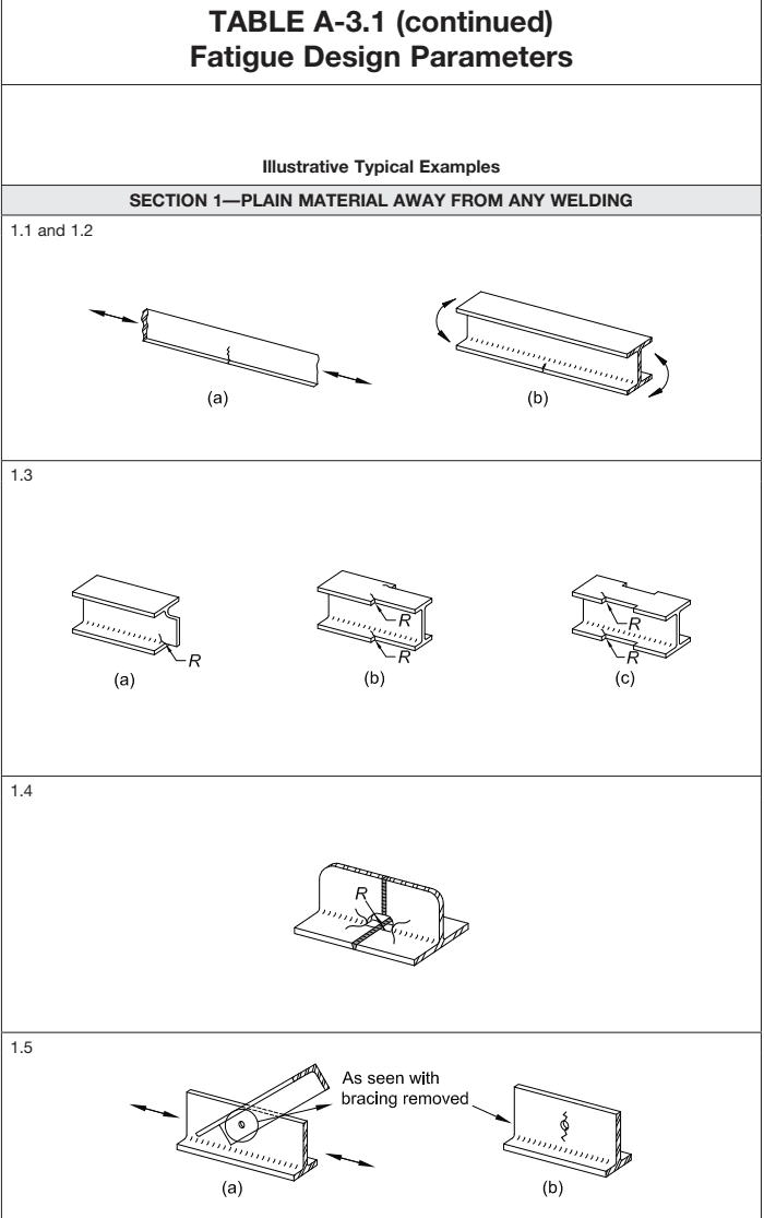
Figure description:
TABLE A-3.1 (continued Fatigue Design Parameters
SECTION 1—PLAIN MATERIAL AWAY FROM ANY WELDING
| Item | Illustrative Typical Examples |
|---|---|
| 1.1 and 1.2 | (a Plate subject to longitudinal stress with a surface crack. (b I-beam subject to bending stress with a crack in the flange.)) |
| 1.3 | (a I-beam with a radius cut into one flange edge. (b I-beam with radius cuts on both edges of one flange. (c I-beam with radius cuts on all four flange edges.))) |
| 1.4 | Angle or T-section with a radius cut and surface crack at the junction of the legs. |
| 1.5 | (a Assembly showing a plate connected to a T-section with longitudinal stress arrows. (b Close-up of the T-section "as seen with bracing removed" showing a vertical surface crack.)) |
Specification for Structural Steel Buildings, August 1, 2022 AMERICAN INSTITUTE OF STEEL CONSTRUCTION
TABLE A-3.1 (continued)
Fatigue Design Parameters
| Description | Stress Category | Constant, Cf | Threshold, FTH, ksi (MPa) | Potential Crack Initiation Point |
|---|---|---|---|---|
| SECTION 2—CONNECTED MATERIAL IN MECHANICALLY FASTENED JOINTS | ||||
| 2.1 Gross area of base metal in lap joints connected by high-strength bolts where the joints satisfy all require- ments for slip-critical connections[a] | B | 12 | 16 (110) | Through gross section not through the hole |
| 2.2 Net area of base metal in lap joints connected by high-strength bolts where the joints satisfy all require- ments for pretensioned connections[b] | B | 12 | 16 (110) | In net section originating at side of hole |
| 2.3 Net section of base metal in exist- ing riveted joints | D | 2.2 | 7 (48) | In net section originating at side of hole |
| 2.4 Net section in base metal of eyebar or pin plate connections | E | 1.1 | 4.5 (31) | In net section originating at side of hole |
[a]Slip-critical connections are required by the RCSC Specification for joints subject to the provisions of this appendix with reversal of the loading direction [see RCSC Specification Section 4.3(1)], and permitted for other loading conditions (see RCSC Specification Section 4.3 Commentary). Holes may be prepared by any method permitted by this Specification.
[b] Pretensioned connections are restricted by the RCSC Specification to cyclically loaded connections where there is no reversal of loading direction [see RCSC Specification Section 4.2(3)]. Holes may be prepared by any method permitted by this Specification but the RCSC Specification requires thermally cut holes to be approved by the engineer of record (see RCSC Specification Section 3.3).
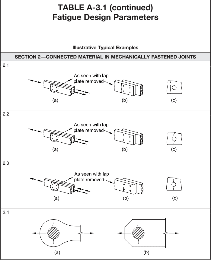
Figure description:
Title: TABLE A-3.1 (continued Fatigue Design Parameters
Section: SECTION 2—CONNECTED MATERIAL IN MECHANICALLY FASTENED JOINTS
Illustrative Typical Examples:
- 2.1, 2.2, 2.3: Isometric and detail views of lap joints under axial tension.
- (a: Assembly showing lap plates and fastener locations.
- (b: View with lap plate removed, highlighting crack initiation at bolt holes.
- (c: Detail of specific crack propagation relative to fastener holes.
- 2.4: Plan views of pin-connected plates (eye-bars and rectangular ends under axial tension.
- (a & (b: Show crack initiation from the edge of the pin hole.
TABLE A-3.1 (continued) Fatigue Design Parameters
| Description | Stress Category | Constant, Cf | Threshold, FTH, ksi (MPa) | Potential Crack Initiation Point |
|---|---|---|---|---|
| SECTION 3—WELDED JOINTS JOINING COMPONENTS OF BUILT-UP MEMBERS | ||||
| 3.1 Base metal and weld metal in mem-bers without attachments built up of plates or shapes connected by con-tinuous longitudinal CJP groove welds, back gouged, and welded from second side, or by continuous fillet welds | B | 12 | 16 (110) | From surface or internal discontinuities in weld |
| 3.2 Base metal and weld metal in mem-bers without attachments built up of plates or shapes, connected by con-tinuous longitudinal CJP groove welds with left-in-place continuous steel backing, or by continuous PJP groove welds | B′ | 6.1 | 12 (83) | From surface or internal discontinuities in weld |
| 3.3 Base metal at the ends of longitudi-nal welds that terminate at weld access holes in connected built-up members, as well as weld toes of fillet welds that wrap around ends of weld access holes | From the weld termination into the web or flange | |||
| Access hole R ≥ 1 in. (25 mm) with radius, R, formed by predrilling, sub-punching and reaming, or thermally cut and ground to bright metal surface | D | 2.2 | 7 (48) | |
| Access hole R ≥ 3/8 in. (10 mm) and the radius, R, need not be ground to a bright metal surface | E′ | 0.39 | 2.6 (18) | |
| 3.4 Base metal at ends of longitudinal intermittent fillet weld segments | E | 1.1 | 4.5 (31) | In connected material at start and stop locations of any weld |
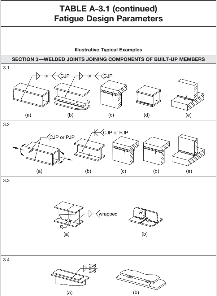
Figure description:
Table: A-3.1 (continued Title: Fatigue Design Parameters Section: SECTION 3—WELDED JOINTS JOINING COMPONENTS OF BUILT-UP MEMBERS
Illustrative Typical Examples:
- 3.1: Longitudinal welds joining components for box and I-beam sections; includes Complete Joint Penetration (CJP weld symbols.
- 3.2: Welds joining components subject to cyclic loading; includes Complete Joint Penetration (CJP or Partial Joint Penetration (PJP weld symbols.
- 3.3: Wrapped weld terminations with specified radius ( on I-beam and T-joint configurations.
- 3.4: Intermittent fillet welds (notated "2-6 / 2-6" joining plate components.
TABLE A-3.1 (continued)
Fatigue Design Parameters
| Description | Stress Category | Constant, Cf | Threshold, FTH, ksi (MPa) | Potential Crack Initiation Point |
|---|---|---|---|---|
| SECTION 3—WELDED JOINTS JOINING COMPONENTS OF BUILT-UP MEMBERS (cont’d) | ||||
| 3.5 Base metal at ends of partial length welded cover plates narrower than the flange having square or tapered ends, with or without welds across the ends | In flange at toe of end weld (if present) or in flange at termination of longitudinal weld | |||
| tf≤0.8 in. (20 mm) | E | 1.1 | 4.5 (31) | |
| tf > 0.8 in. (20 mm) | E' | 0.39 | 2.6 (18) | |
| where tf = thickness of member flange, in. (mm) | ||||
| 3.6 Base metal at ends of partial length welded cover plates or other attach-ments wider than the flange with welds across the ends | In flange at toe of end weld or in flange at termination of longitudinal weld or in edge of flange | |||
| tf≤0.8 in. (20 mm) | E | 1.1 | 4.5 (31) | |
| tf > 0.8 in. (20 mm) | E' | 0.39 | 2.6 (18) | |
| 3.7 Base metal at ends of partial length welded cover plates wider than the flange without welds across the ends tf≤0.8 in. (20 mm) | E' | 0.39 | 2.6 (18) | In edge of flange at end of cover plate weld |
| tf > 0.8 in. (20 mm) is not permitted | None | — | — | |
| SECTION 4—LONGITUDINAL FILLET WELDED END CONNECTIONS | ||||
| 4.1 Base metal at junction of axially loaded members with longitudinally welded end connections; welds are on each side of the axis of the member to balance weld stresses | Initiating from end of any weld termination extending into the base metal | |||
| t≤0.5 in. (13 mm) | E | 1.1 | 4.5 (31) | |
| t > 0.5 in. (13 mm) | E' | 0.39 | 2.6 (18) | |
| where t = connected member thickness, as shown in the Case 4.1 figure, in. (mm) | ||||
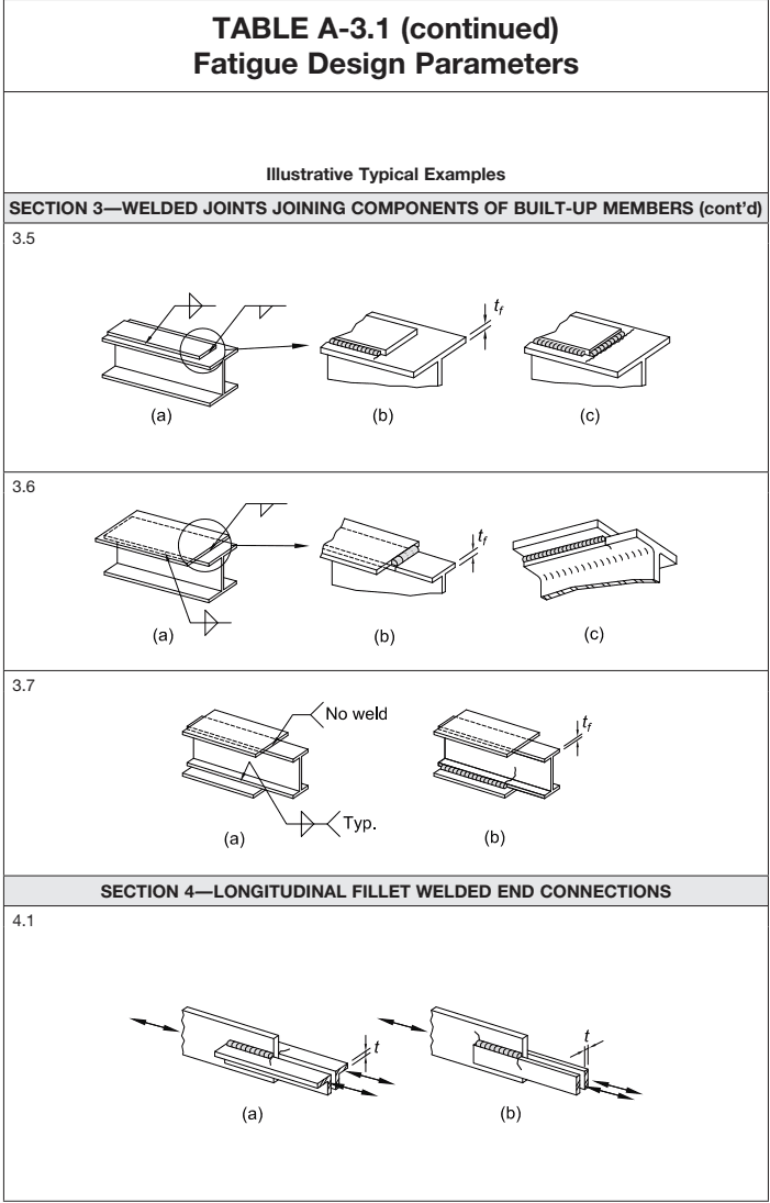
Figure description:
TABLE A-3.1 (continued Fatigue Design Parameters
Illustrative Typical Examples
SECTION 3—WELDED JOINTS JOINING COMPONENTS OF BUILT-UP MEMBERS (cont’d
- 3.5: Illustrates fillet weld details for cover plates on I-beams.
- (a Isometric view showing weld locations.
- (b Detail showing plate thickness and weld termination at the plate edge.
- (c Detail showing a continuous weld around the plate corner.
- 3.6: Illustrates tapered cover plate weld details on I-beams.
- (a Isometric view with welding symbols.
- (b Detail showing plate thickness and weld termination before the tapered end.
- (c Detail showing weld continuing along the tapered section.
- 3.7: Illustrates cover plate details with specified no-weld zones.
- (a Isometric view marking "No weld" at the transverse edge and "Typ." (typical longitudinal welds.
- (b Detail view showing plate thickness and longitudinal fillet welds.
SECTION 4—LONGITUDINAL FILLET WELDED END CONNECTIONS
- 4.1: Illustrates longitudinal fillet welds connecting plates or angles, with arrows indicating applied stress directions.
- (a Lapped connection with welds on both sides and plate thickness .
- (b Alternative lapped connection arrangement with plate thickness .
TABLE A-3.1 (continued)
Fatigue Design Parameters
| Description | Stress Category | Constant, C_f | Threshold, F_TH, ksi (MPa) | Potential Crack Initiation Point |
|---|---|---|---|---|
| SECTION 5—WELDED JOINTS TRANSVERSE TO DIRECTION OF STRESS | ||||
| 5.1 Weld metal and base metal in or adjacent to CJP groove welded splices in plate, rolled shapes, or built-up cross sections with no change in cross section with welds ground essentially parallel to the direction of stress and inspected in accordance with Section 3.6 | B | 12 | 16 (110) | From internal discontinuities in weld metal or along the fusion boundary |
| 5.2 Weld metal and base metal in or adjacent to CJP groove welded splices with welds ground essentially parallel to the direction of stress at transitions in thickness or width made on a slope no greater than 1:2½ and inspected in accordance with Section 3.6 Fy < 90 ksi (620 MPa) | B | 12 | 16 (110) | From internal discontinuities in metal or along the fusion boundary or at start of transition when Fy ≥ 90 ksi (620 MPa) |
| Fy ≥ 90 ksi (620 MPa) | B′ | 6.1 | 12 (83) | |
| 5.3 Base metal and weld metal in or adjacent to CJP groove welded splices with welds ground essentially parallel to the direction of stress at transitions in width made on a radius, R, of not less than 24 in. (600 mm) with the point of tangency at the end of the groove weld and inspected in accordance with Section 3.6 | B | 12 | 16 (110) | From internal discontinuities in weld metal or along the fusion boundary |
| 5.4 Weld metal and base metal in or adjacent to CJP groove welds in T- or corner-joints or splices, without transi-tions in thickness or with transition in thickness having slopes no greater than 1:2½, when weld reinforcement is not removed, and is inspected in accor-dance with Section 3.6 | C | 4.4 | 10 (69) | From weld extending into base metal or into weld metal |
TABLE A-3.1 (continued)
Fatigue Design Parameters
Illustrative Typical Examples
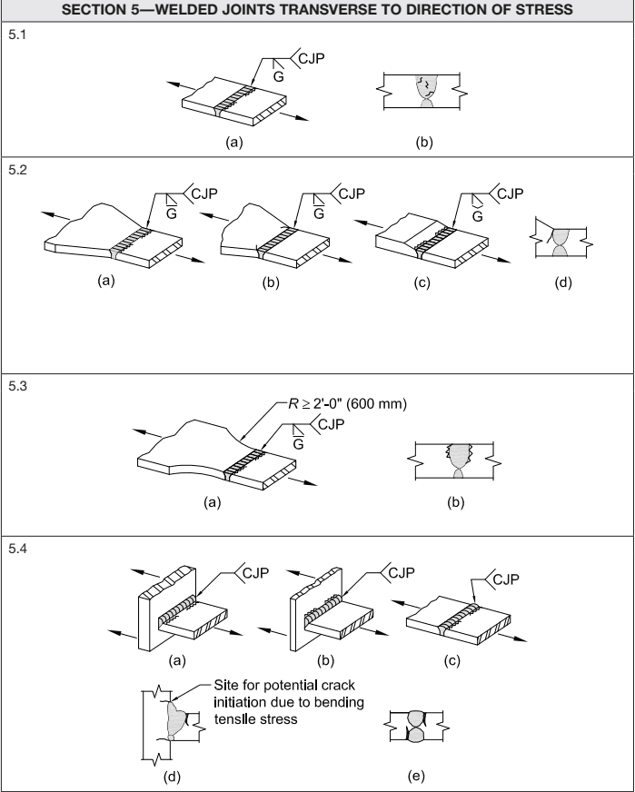
Figure description:
SECTION 5—WELDED JOINTS TRANSVERSE TO DIRECTION OF STRESS
Key Entities and Details:
- Weld Type: Complete Joint Penetration (CJP welds are specified across all examples.
- Stress Direction: Arrows indicate tensile stress applied perpendicular (transverse to the weld axis.
- Finishing: Many examples specify grinding (G to a smooth contour.
- Joint Configurations:
- 5.1: Standard butt joint of equal thickness plates.
- 5.2: Butt joints between plates of varying thicknesses or edge preparations.
- 5.3: Transition between plates of different widths with a specified radius: (600 mm.
- 5.4: Corner joints and T-joints.
- Structural Integrity: Section 5.4(d identifies a "Site for potential crack initiation due to bending tensile stress" located at the weld toe/root interface.
TABLE A-3.1 (continued)
Fatigue Design Parameters
| Description | Stress Category | Constant, Cf | Threshold, FTH, ksi (MPa) | Potential Crack Initiation Point |
|---|
| Description | Stress Category | Constant, Cf | FTH, ksi (MPa) | Potential Crack Initiation Point |
|---|---|---|---|---|
| SECTION 5—WELDED JOINTS TRANSVERSE TO DIRECTION OF STRESS (cont’d) | ||||
| 5.5 Base metal and weld metal in or ad-adjacent to transverse CJP groove welded butt splices with backing left in place Tack welds inside groove Tack welds outside the groove and not closer than 1/2 in. (13 mm) to the edge of base metal | D | 2.2 | 7 (48) | From the toe of the groove weld or the toe of the weld attaching backing when applicable |
| E | 1.1 | 4.5 (31) | ||
| 5.6 Base metal and weld metal at transverse end connections of tension-loaded plate elements using PJP groove welds in butt, T-, or corner-joints, with reinforcing or contouring fillets; FSR shall be the smaller of the toe crack or root crack allowable stress range Crack initiating from weld toe Crack initiating from weld root | C | 4.4 | 10 (69) | Initiating from weld toe extending into base metal |
| C′ | See Eq. A-3-3 or A-3-3M | None | Initiating at weld root extending into and through weld | |
| 5.7 Base metal and weld metal at transverse end connections of tension-loaded plate elements using a pair of fillet welds on opposite sides of the plate; FSR shall be the smaller of the weld toe crack or weld root crack allowable stress range Crack initiating from weld toe Crack initiating from weld root | C | 4.4 | 10 (69) | Initiating from weld toe extending into base metal |
| C′′ | See Eq. A-3-5 or A-3-5M | None | Initiating at weld root extending into and through weld | |
| 5.8 Base metal of tension-loaded plate elements, and on built-up shapes and rolled beam webs or flanges at toe of transverse fillet welds adjacent to welded transverse stiffeners | C | 4.4 | 10 (69) | From geometrical discontinuity at toe of fillet extending into base metal |
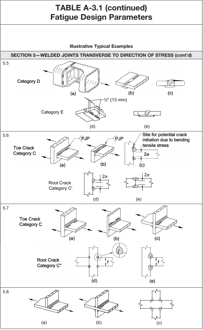
Figure description:
TABLE A-3.1 (continued Fatigue Design Parameters - Illustrative Typical Examples SECTION 5—WELDED JOINTS TRANSVERSE TO DIRECTION OF STRESS (cont’d
- 5.5 Welded Joints
- Category D: (a HSS welded connection; (b, (c Full penetration groove welds ground flush.)))
- Category E: (d, (e Welds with reinforcement; specifies 1/2" (13 mm dimension.)))
- 5.6 Partial Joint Penetration (PJP Welded Joints
- Toe Crack Category C: (a, (b T-joints with PJP welds; (c Cross-section showing crack initiation site from bending tensile stress, dimension .)))
- Root Crack Category C': (d, (e Cross-sections with dimension .))
- 5.7 Welded Joints
- Toe Crack Category C: (a, (b T-joints; (c Cruciform joint.)))
- Root Crack Category C'': (d, (e Cross-sections with dimension ; includes a magnified view of a root crack.))
- 5.8 Fillet Welded Joints
- (a T-joint with fillet welds.
- (b Cruciform joint with fillet welds.
- (c Cross-section view of fillet-welded cruciform joint.
Specification for Structural Steel Buildings, August 1, 2022 AMERICAN INSTITUTE OF STEEL CONSTRUCTION
TABLE A-3.1 (continued)
Fatigue Design Parameters
| Description | Stress Category | Constant, Cf | Threshold, FTH, ksi (MPa) | Potential Crack Initiation Point |
|---|
| Description | Category | Cf | (MPa) | Initiation Point |
|---|---|---|---|---|
| SECTION 6—BASE METAL AT WELDED TRANSVERSE MEMBER CONNECTIONS | ||||
| 6.1 Base metal of equal or unequal thick-ness at details attached by CJP groove welds subjected to longitudinal loading only when the detail embodies a transition radius, R, with the weld termination ground smooth and inspected in accordance with Section 3.6 | Near point of tangency of radius at edge of member | |||
| R ≥ 24 in. (600 mm) | B | 12 | 16 (110) | |
| 6 in. ≤ R < 24 in. (150 mm ≤ R < 600 mm) | C | 4.4 | 10 (69) | |
| 2 in. ≤ R < 6 in. (50 mm ≤ R < 150 mm) | D | 2.2 | 7 (48) | |
| R < 2 in. (50 mm) | E | 1.1 | 4.5 (31) | |
| 6.2 Base metal at details of equal thick-ness attached by CJP groove welds, sub-jected to transverse loading, with or without longitudinal loading, when the detail em-bodies a transition radius, R, with the weld termination ground smooth and inspected in accordance with Section 3.6 | Near point of tangency of radius or in the weld or at fusion boundary of member or attachment | |||
| (a) When weld reinforcement is removed | ||||
| R ≥ 24 in. (600 mm) | B | 12 | 16 (110) | |
| 6 in. ≤ R < 24 in. (150 mm ≤ R < 600 mm) | C | 4.4 | 10 (69) | |
| 2 in. ≤ R < 6 in. (50 mm ≤ R < 150 mm) | D | 2.2 | 7 (48) | |
| R < 2 in. (50 mm) | E | 1.1 | 4.5 (31) | |
| (b) When weld reinforcement is not re-moved | At toe of the weld, either along edge of member or the attachment | |||
| R ≥ 6 in. (150 mm) | C | 4.4 | 10 (69) | |
| 2 in. ≤ R < 6 in. (50 mm ≤ R < 150 mm) | D | 2.2 | 7 (48) | |
| R < 2 in. (50 mm) | E | 1.1 | 4.5 (31) | |
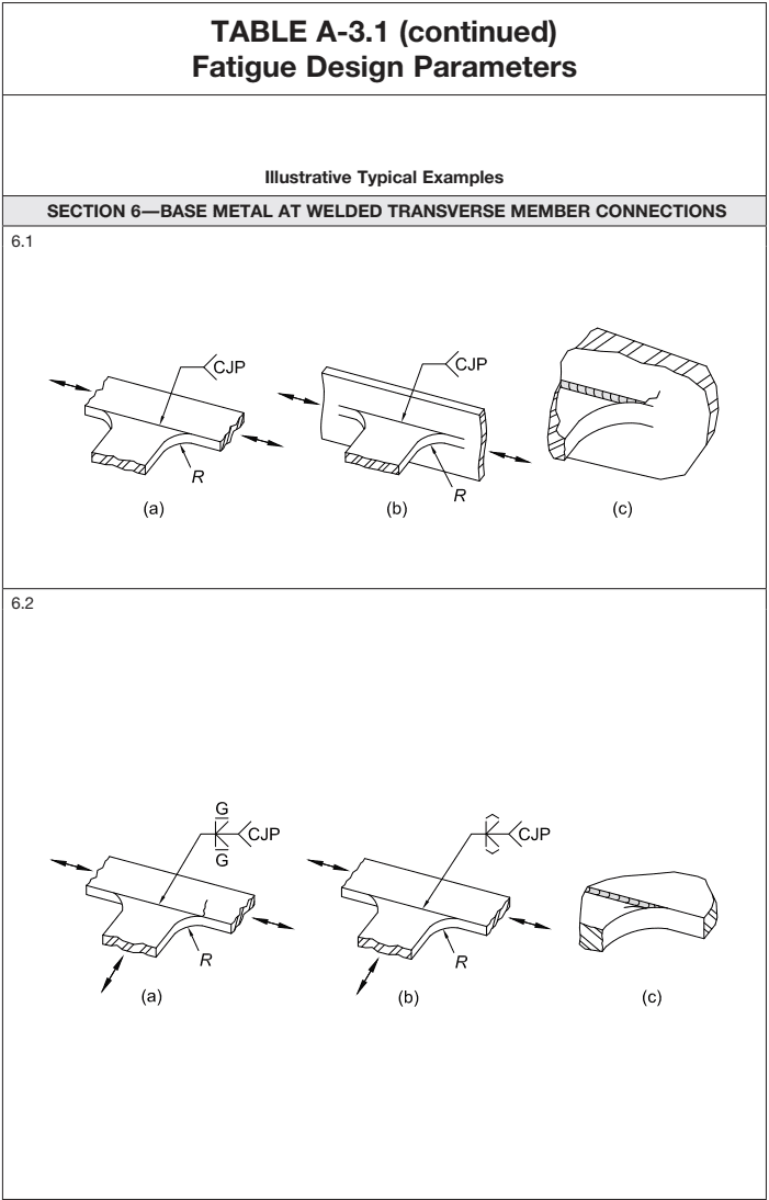
Figure description:
TABLE A-3.1 (continued: Fatigue Design Parameters Section 6—Base Metal at Welded Transverse Member Connections
- Overview: Provides illustrative typical examples of welded joint configurations and stress patterns for fatigue design.
- Subsection 6.1:
- Components: Features isometric views (a, b and a cross-section (c.
- Weld Type: Complete Joint Penetration (CJP.
- Key Features: Radius (R transitions at the connection; arrows indicating longitudinal and transverse stress.
- Subsection 6.2:
- Components: Features isometric views (a, b and a cross-section (c.
- Weld Type: CJP welds with finishing requirements (indicated by "G" for grinding flush.
- Key Features: Radius (R transitions; arrows indicating complex, multi-axial stress directions.
TABLE A-3.1 (continued)
Fatigue Design Parameters
| Description | Stress Category | Constant, Cf | Threshold, FTH, ksi (MPa) | Potential Crack Initiation Point |
|---|---|---|---|---|
| SECTION 6—BASE METAL AT WELDED TRANSVERSE MEMBER CONNECTIONS (cont’d) | ||||
| 6.3 Base metal at details of unequal thick-ness attached by CJP groove welds, sub-jected to transverse loading, with or without longitudinal loading, when the detail em-bodies a transition radius, R, with the weld termination ground smooth and in accor-dance with Section 3.6 | ||||
| (a) When weld reinforcement is removed | ||||
| R > 2 in. (50 mm) | D | 2.2 | 7 (48) | At toe of weld along edge of thinner material |
| R ≤ 2 in. (50 mm) | E | 1.1 | 4.5 (31) | In weld termi- nation in small radius |
| (b) When reinforcement is not removed | ||||
| Any radius | E | 1.1 | 4.5 (31) | At toe of weld along edge of thinner material |
| 6.4 Base metal of equal or unequal thickness, subjected to longitudinal stress at transverse members, with or without transverse stress, attached by fillet or PJP groove welds para-llel to direction of stress when the detail embodies a transition radius, R, with weld termination ground smooth | Initiating in base metal at the weld termina-tion or at the toe of the weld extending into the base metal | |||
| R > 2 in. (50 mm) | D | 2.2 | 7 (48) | |
| R ≤ 2 in. (50 mm) | E | 1.1 | 4.5 (31) | |
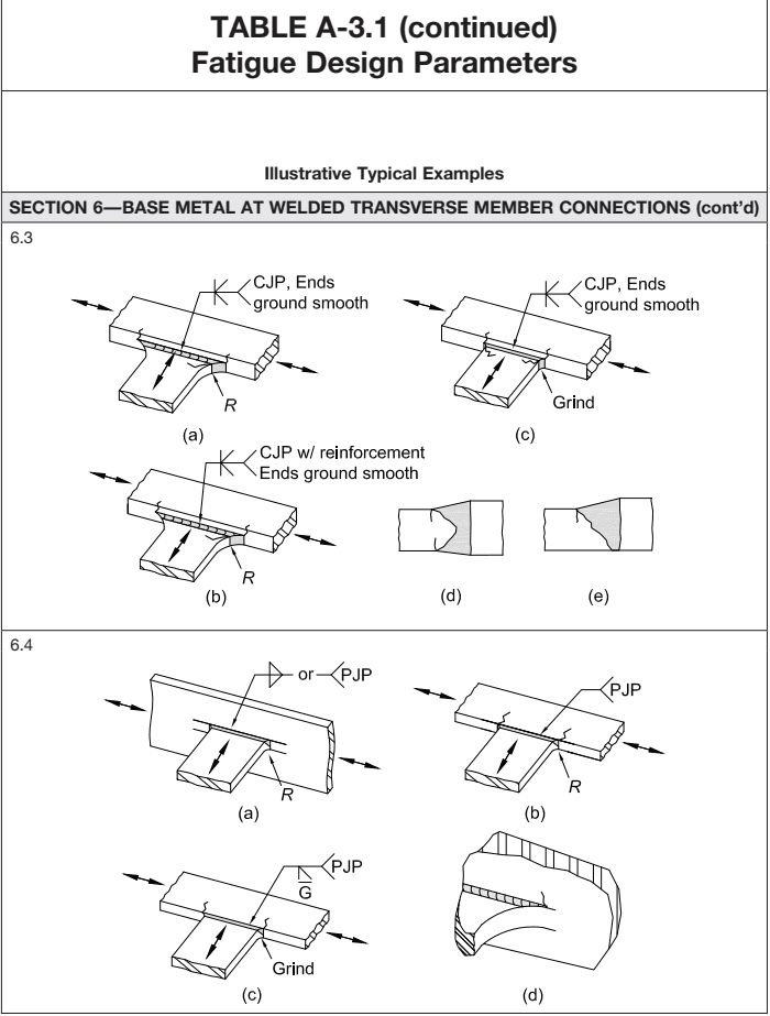
Figure description:
TABLE A-3.1: Fatigue Design Parameters Section 6—Base Metal at Welded Transverse Member Connections (cont’d
6.3 Illustrative Typical Examples
- (a: CJP (Complete Joint Penetration weld with radius ; ends ground smooth.
- (b: CJP weld with reinforcement; ends ground smooth; includes radius .
- (c: CJP weld with ends ground smooth; specific "Grind" callout on the connection corner.
- (d & (e: Detailed cross-sectional profiles of weld terminations.
6.4 Illustrative Typical Examples
- (a: Transverse connection using either a fillet weld or PJP (Partial Joint Penetration weld with radius .
- (b: PJP weld connection with radius .
- (c: PJP weld with specified grinding (indicated by "G" symbol and "Grind" label.
- (d: Isometric detail of a curved transverse member connection.
TABLE A-3.1 (continued)
Fatigue Design Parameters
| Description | Stress Category | Constant, Cf | Threshold, FTH, ksi (MPa) | Potential Crack Initiation Point |
|---|---|---|---|---|
| SECTION 7—BASE METAL AT SHORT ATTACHMENTS[a] | ||||
| 7.1 Base metal subjected to longitudinal loading at details with welds parallel or transverse to the direction of stress, with or without transverse load on the detail, where the detail embodies no transition radius, R, and with detail length, a, in direction of stress and thickness of the attachment, b a < 2 in. (50 mm) for any thickness, b | C | 4.4 | 10 (69) | Initiating in base metal at the weld termina-tion or at the toe of the weld extending into the base metal |
| D | 2.2 | 7 (48) | ||
| E | 1.1 | 4.5 (31) | ||
| E′ | 0.39 | 2.6 (18) | ||
| 7.2 Base metal subjected to longitudinal stress at details attached by fillet or PJP groove welds, with or without transverse load on detail, when the detail embodies a transition radius, R, with weld termination ground smooth R > 2 in. (50 mm) | D | 2.2 | 7 (48) | Initiating in base metal at the weld termina- tion, extending into the base metal |
| E | 1.1 | 4.5 (31) | ||
[a]“Attachment,” as used herein, is defined as any steel detail welded to a member that causes a deviation in the stress flow in the member and, thus, reduces the fatigue resistance. The reduction is due to the presence of the attachment, not due to the loading on the attachment.
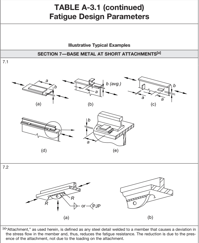
Figure description:
Table Title: TABLE A-3.1 (continued Fatigue Design Parameters Section: SECTION 7—BASE METAL AT SHORT ATTACHMENTS
Key Information:
- Subsection 7.1: Illustrative examples (a through (e of short attachments on various structural members (plates, beams. Dimensions a (length along stress path and b (thickness/height are used to characterize the attachment geometry.)))))
- Subsection 7.2: Illustrative examples (a and (b of attachments with curved or radiused transitions (R and specific weld requirements (e.g., PJP - Partial Joint Penetration.
- Footnote [a: Defines "Attachment" as any steel detail welded to a member that causes stress flow deviation, thereby reducing fatigue resistance due to the presence of the attachment itself rather than its loading.
| TABLE A-3.1 (continued) Fatigue Design Parameters | ||||
|---|---|---|---|---|
| Description | Stress Category | Constant, Cf | Threshold, FTH, ksi (MPa) | Potential Crack Initiation Point |
| SECTION 8—MISCELLANEOUS | ||||
| 8.1 Base metal at steel headed stud anchors attached by fillet weld or auto-matic stud welding | C | 4.4 | 10 (69) | At toe of weld in base metal |
| 8.2 Shear on throat of any fillet weld, continuous or intermittent, longitudinal or transverse | F | See Eq. A-3-2 or A-3-2M | See Eq. A-3-2 or A-3-2M | Initiating at the root of the fillet weld, extending into the weld |
| 8.3 Base metal at plug or slot welds | E | 1.1 | 4.5 (31) | Initiating in the base metal at the end of the plug or slot weld, extending into the base metal |
| 8.4 Shear on plug or slot welds | F | See Eq. A-3-2 or A-3-2M | See Eq. A-3-2 or A-3-2M | Initiating in the weld at the faying surface, extending into the weld |
| 8.5 High-strength bolts, common bolts, threaded anchor rods, and hanger rods, whether pretensioned in accordance with Table J3.1 or J3.1M, or snug-tight-ened with cut, ground, or rolled threads; stress range on tensile stress area due to applied cyclic load plus prying action, when applicable | G | 0.39 | 7 (48) | Initiating at the root of the threads, extending into the fastener |
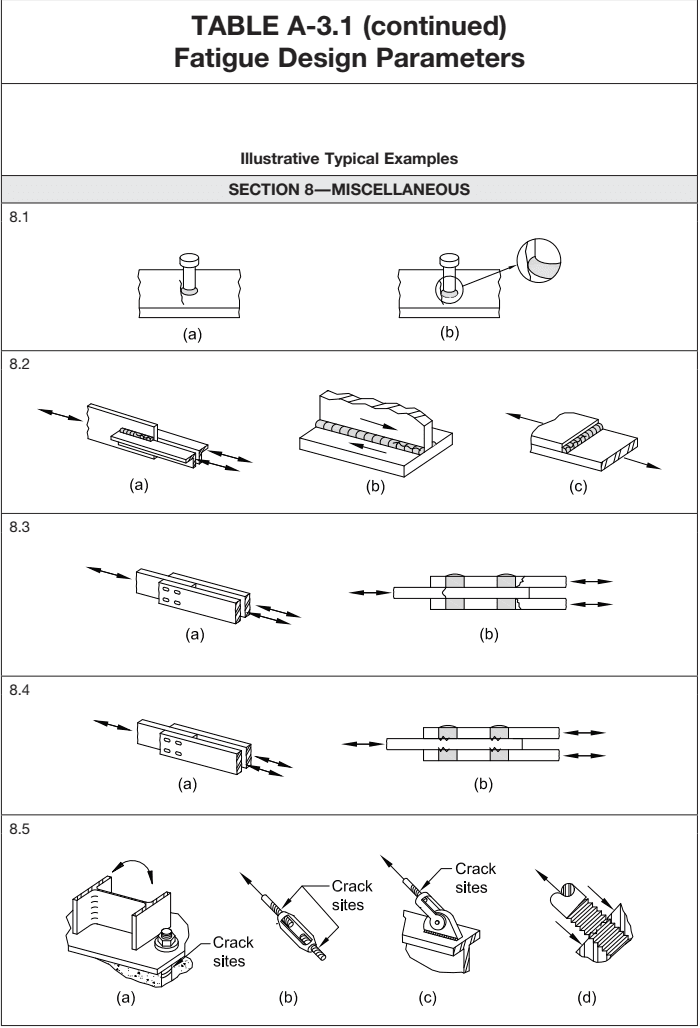
Figure description:
TABLE A-3.1 (continued Fatigue Design Parameters SECTION 8—MISCELLANEOUS: Illustrative Typical Examples
- 8.1: Mechanical fasteners (bolts or rivets in a base plate.
- 8.2: Welded joints including longitudinal fillet welds and transverse groove welds under tension.
- 8.3 & 8.4: Bolted or riveted lap joints and splice plates subjected to cyclic axial loading.
- 8.5: Various mechanical assemblies with identified potential Crack sites:
- (a Column base plate assembly.
- (b Turnbuckle.
- (c Eyebolt/pin connection.
- (d Threaded rod or bolt.