4.3design by qualification testing
PDF page 314 · AISC 360-22
4.3.1 Qualification Standards
Structural members and components in steel buildings shall be qualified for the rating period in conformance with ASTM E119 or ANSI/UL 263. Demonstration of compliance with these requirements using the procedures specified for steel construction in Section 5 of Standard Calculation Methods for Structural Fire Protection (ASCE/ SEI/SFPE 29) is permitted. It is also permitted to demonstrate equivalency to such standard fire-resistance ratings using the advanced analysis methods in Section 4.2 in combination with the fire exposure specified in ASTM E119 or ANSI/UL 263 as the design-basis fire.
User Note: There are other standard fire exposures that are more severe than that prescribed in ASTM E119, for example the hydrocarbon pool fire scenario defined in ASTM E1529 (UL 1709). Fire-resistance ratings developed on the basis of ASTM E119 are not directly substitutable for such more demanding conditions.
The generic steel assemblies described in Table A-4.3.1 shall be deemed to have the fire-resistance ratings prescribed therein.
4.3.2 Structural Steel Assemblies
The provisions of this section contain procedures by which the standard fire-resistance ratings of structural steel assemblies are established by calculations. Use of these provisions is permitted in place of and/or as a supplement to published fire-resistive assemblies based on ASTM E119 or ANSI/UL 263. The installation of the fire-protection material shall comply with the applicable requirements of the building code, the referenced approved assemblies, and manufacturer instructions.
The weight-to-heated-perimeter ratios, , and area-to-heated-perimeter ratios, , shall be determined in accordance with the definitions given in this section. As used in these sections, is the average weight of a shape in pounds per linear foot and is the area in square inches. The heated perimeter, or , is the inside perimeter of the fire-resistant material or exterior contour of the steel shape in inches, as defined for each type of member.
4.3.2a Steel Columns
The fire-resistance ratings of columns shall be based on the size of the member and the type of protection provided in accordance with this section.
The application of these procedures for noncomposite steel column assemblies shall be limited to designs in which the fire-resistant material is not designed to carry any of the load acting on the column.
TABLE A-4.3.1
Minimum Fire Protection and Fire-Resistance Ratings of Steel Assemblies[e]
| Assembly | Item Number | Fire-Protection Material Used | Minimum Thickness of Insulating Material for Fire-Resistance Times, in. (mm) | |||
|---|---|---|---|---|---|---|
| 4 hrs | 3 hrs | 2 hrs | 1 hr | |||
| 1. Steel columns and all of primary trusses | 1-1.1 | Carbonate, lightweight, and sand-light-weight aggregate concrete, members 6 in. × 6 in. (150 mm × 150 mm) or greater (not including sandstone, granite, and siliceous gravel)[a] | 2½ (63) | 2 (50) | 1½ (38) | 1 (25) |
| 1-1.2 | Carbonate, lightweight, and sand-light-weight aggregate concrete, members 8 in. × 8 in. (200 mm × 200 mm) or greater (not including sandstone, granite, and siliceous gravel)[a] | 2 (50) | 1½ (38) | 1 (25) | 1 (25) | |
| 1-1.3 | Carbonate, lightweight, and sand-light-weight aggregate concrete, members 12 in. × 12 in. (300 mm × 300 mm) or greater (not including sandstone, granite, and siliceous gravel)[a] | 1½ (38) | 1 (25) | 1 (25) | 1 (25) | |
| 1-1.4 | Siliceous aggregate concrete and concrete excluded in Item 1-1.1, members 6 in. × 6 in. (150 mm × 150 mm) or greater[a] | 3 (75) | 2 (50) | 1½ (38) | 1 (25) | |
| 1-1.5 | Siliceous aggregate concrete and concrete excluded in Item 1-1.1, members 8 in. × 8 in. (200 mm × 200 mm) or greater[a] | 2½ (63) | 2 (50) | 1 (25) | 1 (25) | |
| 1-1.6 | Siliceous aggregate concrete and concrete excluded in Item 1-1.1, members 12 in. × 12 in. (300 mm × 300 mm) or greater[a] | 2 (50) | 1 (25) | 1 (25) | 1 (25) | |
| 1-2.1 | Clay or shale brick with brick and mortar fill[a] | 3¾ (94) | – | – | 2¼ (56) | |
| 1-4.1 | Cement plaster over metal lath wire tied to ¾ in. (19 mm) cold-rolled vertical channels with 0.049 in. (1.2 mm) (No. 18 B.W. Gage) wire ties spaced 3 to 6 in. (75 to 150 mm) on center; plaster mixed 1:2.5 by volume, cement to sand | – | – | 2½[b] (63)[b] | ⅞ (22) | |
B.W. = Birmingham Wire
[a] Reentrant parts of protected members to be filled solidly.
[b]Two layers of equal thickness with a 3/4 in. (19 mm) airspace between.
e]Generic fire-resistance ratings (those not designated as PROPRIETARY* in the listing) in GA-600 shall be accepted as if herein listed.
TABLE A-4.3.1 (continued) Minimum Fire Protection and Fire-Resistance Ratings of Steel Assemblies[e]
| Assembly | Item Number | Fire-Protection Material Used | Minimum Thickness of Insulating Material for Fire-Resistance Times, in. (mm) | |||
|---|---|---|---|---|---|---|
| 4 hrs | 3 hrs | 2 hrs | 1 hr | |||
| 1. Steel columns and all of primary trusses | 1-5.1 | Vermiculite concrete, 1:4 mix by volume over paperbacked wire fabric lath wrapped directly around column with additional 2 × 2 in. 0.065 / 0.065 in. (No. 16/16 B.W. Gage) (50 × 50 mm 1.7 / 1.7 mm) wire fabric placed ¾ in. (19 mm) from outer concrete surface; wire fabric tied with 0.049 in. (1.2 mm) (No. 18 B.W. Gage) wire spaced 6 in. (150 mm) on center for inner layer and 2 in. (50 mm) on center for outer layer | 2 (50) | – | – | – |
| 1-6.1 | Perlite or vermiculite gypsum plaster over metal lath wrapped around column and furred 1¼ in. (31 mm) from column flanges; sheets lapped at ends and tied at 6 in. (150 mm) intervals with 0.049 in. (1.2 mm) (No. 18 B.W. Gage) tie wire; plaster pushed through to flanges | 1½ (38) | 1 (25) | – | – | |
| 1-6.2 | Perlite or vermiculite gypsum plaster over self-furring metal lath wrapped directly around column, lapped 1 in. (25 mm) and tied at 6 in. (150 mm) intervals with 0.049 in. (1.2 mm) (No. 18 B.W. Gage) wire | 1¾ (44) | 1⅜ (35) | 1 (25) | – | |
| 1-6.3 | Perlite or vermiculite gypsum plaster on metal lath applied to ¾ in. (19 mm) cold-rolled channels spaced 24 in. (600 mm) apart vertically and wrapped flatwise around column | 1½ (38) | – | – | – | |
| 1-6.4 | Perlite or vermiculite gypsum plaster over two layers of ½ in. (13 mm) plain full-length gypsum lath applied tight to column flanges; lath wrapped with 1 in. (25 mm) hexagonal mesh of 0.035 in. (0.89 mm) (No. 20 Gage) wire and tied with doubled 0.049-in.- (1.2-mm-) diameter (No. 18 B.W. Gage) wire ties spaced 23 in. (580 mm) on center; for three-coat work, the plaster mix for the second coat shall not exceed 100 pounds (45 kg) of gypsum to 2.5 ft³ (0.071 m³) of aggregate for the 3 hour system | 2½ (63) | 2 (50) | – | – | |
B.W. = Birmingham Wire [e]Generic fire-resistance ratings (those not designated as PROPRIETARY* in the listing) in GA-600 shall be accepted as if herein listed.
TABLE A-4.3.1 (continued)
Minimum Fire Protection and Fire-Resistance Ratings of Steel Assemblies[e]
| Assembly | Item Number | Fire-Protection Material Used | Minimum Thickness of Insulating Material for Fire-Resistance Times, in. (mm) | |||
|---|---|---|---|---|---|---|
| 4 hrs | 3 hrs | 2 hrs | 1 hr | |||
| 1. Steel columns and all of primary trusses | 1-6.5 | Perlite or vermiculite gypsum plaster over one layer of 1/2 in. (13 mm) plain full-length gypsum lath applied tight to column flanges. Lath tied with doubled 0.049 in. (1.2 mm) (No. 18 B.W. Gage) wire ties spaced 23 in. (580 mm) on center and scratch coat wrapped with 1 in. (25 mm) hexagonal mesh 0.035 in. (0.89 mm) (No. 20 B.W. Gage) wire fabric; for three-coat work, the plaster mix for the second coat shall not exceed 100 pounds (45 kg) of gypsum to 2.5 ft3 (0.071 m3) of aggregate | – | 2 (50) | – | – |
| 1-7.1 | Multiple layers of 1/2 in. (13 mm) gypsum wallboard[c] adhesively[d] secured to column flanges and successive layers; wallboard applied without horizontal joints; corner edges of each layer staggered; wallboard layer below outer layer secured to column with doubled 0.049 in. (1.2 mm) (No. 18 B.W. Gage) steel wire ties spaced 15 in. (380 mm) on center; exposed corners taped and treated | – | – | 2 (50) | 1 (25) | |
| 1-7.2 | Three layers of 5/8 in. (16 mm) Type X gypsum wallboard;[c] first and second layer held in place by 1/8-in.-diameter by 13/8-in.-long (3-mm-diameter by 35-mm-long) ring shank nails with 5/16-in.- (8-mm-) diameter heads spaced 24 in. (600 mm) on center at corners; middle layer also secured with metal straps at mid-height and 18 in. (450 mm) from each end, and by metal corner bead at each corner held by the metal straps; third layer attached to corner bead with 1-in.- (25-mm-) long gypsum wallboard screws spaced 12 in. (300 mm) on center | – | – | 17/8 (47) | – | |
B.W. = Birmingham Wire
An approved adhesive qualified under ASTM E119 or ANSI/SE 266. [9]Generic fire-resistance ratings (those not designated as PROPRIETARY* in the listing) in GA-600 shall be accepted as if herein listed.
TABLE A-4.3.1 (continued) Minimum Fire Protection and Fire-Resistance Ratings of Steel Assemblies[e]
| Assembly | Item Number | Fire-Protection Material Used | Minimum Thickness of Insulating Material for Fire- Resistance Times, in. (mm) | |||
|---|---|---|---|---|---|---|
| 4 hrs | 3 hrs | 2 hrs | 1 hr | |||
| 1. Steel columns and all of primary trusses | 1-7.3 | Three layers of 5/8 in. (16 mm) Type X gypsum wallboard,[c] each layer screw attached to 15/8 in. (41 mm) steel studs, 0.018 in. (0.46 mm) thick (No. 25 carbon sheet steel gage) at each corner of column; middle layer also secured with 0.049 in. (1.2 mm) (No. 18 B.W. Gage) double-strand steel wire ties, 24 in. (600 mm) on center; screws are No. 6 by 1 in. (25 mm) spaced 24 in. (600 mm) on center for inner layer, No. 6 by 15/8 in. (41 mm) spaced 12 in. (300 mm) on center for middle layer and No. 8 by 21/4 in. (56 mm) spaced 12 in. (300 mm) on center for outer layer | – | 17/8 (47) | – | – |
| 1-9.1 | Minimum W8×35 wide-flange steel column (W/D ≥ 0.75; W/D is the weight-to-heated perimeter ratio, where W = weight of shape and D = heated perimeter) with each web cavity filled even with the flange tip with normal weight carbonate or siliceous aggregate concrete, 3,000 psi specified compressive strength with 145 pcf ± 3 pcf unit weight (21 MPa specified compressive strength with 2 300 kg/m³ ± 48 kg/m³ unit weight). Reinforce the concrete in each web cavity with minimum No. 4 (13 mm) deformed reinforcing bar installed vertically and centered in the cavity, and secured to the column web with minimum No. 2 (6 mm) horizontal deformed reinforcing bar welded to the web every 18 in. (450 mm) on center vertically. As an alternative to the No. 4 (13 mm) rebar, 3/4-in.-diameter by 3-in.-long (19-mm-diameter by 75-mm-long) headed studs, spaced at 12 in. (300 mm) on center vertically, shall be welded on each side of the web midway between the column flanges. | – | – | – | See Note [f] | |
B.W. = Birmingham Wire
TABLE A-4.3.1 (continued)
Minimum Fire Protection and Fire-Resistance Ratings of Steel Assemblies[e]
| Assembly | Item Number | Fire-Protection Material Used | Minimum Thickness of Insulating Material for Fire-Resistance Times, in. (mm) | |||
|---|---|---|---|---|---|---|
| 4 hrs | 3 hrs | 2 hrs | 1 hr | |||
| 2. Webs or flanges of steel beams and girders | 2-1.1 | Carbonate, lightweight, and sand-light-weight aggregate concrete (not including sandstone, granite, and siliceous gravel) with 3 in. (75 mm) or finer metal mesh placed 1 in. (25 mm) from the finished surface anchored to the top flange and providing not less than 0.025 in.² of steel area per ft (53 mm²/m) in each direction | 2 (50) | 1½ (38) | 1 (25) | 1 (25) |
| 2-1.2 | Siliceous aggregate concrete and con-crete excluded in Item 2-1.1 with 3 in. (75 mm) or finer metal mesh placed 1 in. (25 mm) from the finished surface anchored to the top flange and providing not less than 0.025 in.² of steel area per ft (53 mm²/m) in each direction | 2½ (63) | 2 (50) | 1½ (38) | 1 (25) | |
| 2-2.1 | Cement plaster on metal lath attached to ¾ in. (19 mm) cold-rolled channels with 0.04 in. (1 mm) (No. 18 B.W. Gage) wire ties spaced 3 in. to 6 in. (75 mm to 150 mm) on center; plaster mixed 1:2.5 by volume, cement to sand | – | – | 2½[b] (63)[b] | ⅞ (22) | |
| 2-3.1 | Vermiculite gypsum plaster on a metal lath cage, wire tied to 0.165 in. (4.2 mm) diameter (No. 8 B.W. Gage) steel wire hangers wrapped around beam and spaced 16 in. (400 mm) on center; metal lath ties spaced approximately 5 in. (125 mm) on center at cage sides and bottom | – | ⅞ (22) | – | – | |
B.W. = Birmingham Wire [b]Two layers of equal thickness with a 3/4 in. (19 mm) airspace between.
e]Generic fire-resistance ratings (those not designated as PROPRIETARY* in the listing) in GA-600 shall be accepted as if herein listed.
TABLE A-4.3.1 (continued) Minimum Fire Protection and Fire-Resistance Ratings of Steel Assemblies[e]
| Assembly | Item Number | Fire-Protection Material Used | Minimum Thickness of Insulating Material for Fire-Resistance Times, in. (mm) | |||
|---|---|---|---|---|---|---|
| 4 hrs | 3 hrs | 2 hrs | 1 hr | |||
| 2. Webs or flanges of steel beams and girders | 2-4.1 | Two layers of 5/8 in. (16 mm) Type X gypsum wallboard[c] are attached to U-shaped brackets spaced 24 in. (600 mm) on center. 0.018-in.- (0.46-mm-) thick (No. 25 carbon sheet steel gage), 15/8-in.-deep by 1 in. (41-mm-deep by 25 mm) galvanized steel runner channels are first installed parallel to and on each side of the top beam flange to provide a 1/2 in. (13 mm) clearance to the flange. The channel runners are attached to steel deck or concrete floor con- struction with approved fasteners spaced 12 in. (300 mm) on center. U-shaped brackets are formed from members identical to the chan- nel runners. At the bent portion of the U-shaped bracket, the flanges of the channel are cut out so that 15/8-in.- (41-mm-) deep corner channels can be inserted without attachment parallel to each side of the lower flange. As an alternative, 0.021 in. (0.53 mm) thick (No. 24 carbon sheet steel gage) 1 in. × 2 in. (25 mm × 50 mm) runner and corner angles shall be used in lieu of channels, and the web cutouts in the U-shaped brackets shall not be required. Each angle is attached to the bracket with 1/2-in.- (13-mm-) long, No. 8, self-drilling screws. The vertical legs of the U-shaped bracket are attached to the runners with one 1/2-in.- (13-mm-) long, No. 8, self-drilling screw. The completed steel framing provides a 21/8 in. (53 mm) and 11/2 in. (38 mm) space between the inner layer of wallboard and the sides and bot- tom of the steel beam, respectively. The inner layer of wallboard is attached to the top runners and bottom corner channels or corner angles with 11/4-in.- (31-mm-) long, No. 6, self-drilling screws spaced 16 in. (400 mm) on center. The outer layer of wallboard is applied with 13/4-in.- (44-mm-) long, No. 6, self-drilling screws spaced 8 in. (200 mm) on center. The bottom corners are reinforced with metal corner beads. | – | – | 11/4 (31) | – |
B.W. = Birmingham Wire
e)Generic fire-resistance ratings (those not designated as PROPRIETARY* in the listing) in GA-600 shall be accepted as if herein listed.
TABLE A-4.3.1 (continued)
Minimum Fire Protection and Fire-Resistance Ratings of Steel Assemblies[e]
| Assembly | Item Number | Fire-Protection Material Used | Minimum Thickness of Insulating Material for Fire-Resistance Times, in. (mm) | |||
|---|---|---|---|---|---|---|
| 4 hrs | 3 hrs | 2 hrs | 1 hr | |||
| 2. Webs or flanges of steel beams and girders | 2-4.2 | Three layers of 5/8 in. (16 mm) Type X gypsum wallboard[c] attached to a steel suspension system as described in Item 2-4.1 utilizing the 0.018-in.- (0.46-mm-) thick (No. 25 carbon sheet steel gage), 1 in. × 2 in. (25 mm x 50 mm), lower corner angles. The framing is located so that a 21/8 in. (53 mm) and 2 in. (50 mm) space is provided between the inner layer of wallboard and the sides and bottom of the beam, respectively. The first two layers of wallboard are attached as described in Item 2-4.1. A layer of 0.035-in.- (0.89-mm-) thick (No. 20 B.W. Gage), 1 in. (25 mm) hexagonal, galvanized wire mesh is applied under the soffit of the middle layer and up the sides approximately 2 in. (50 mm). The mesh is held in posi- tion with the No. 6 15/8-in.- (41-mm-) long screws installed in the vertical leg of the bottom corner angles. The outer layer of wallboard is attached with No. 6 21/4-in.- (56-mm-) long screws spaced 8 in. (200 mm) on center. One screw is also installed at the mid-depth of the bracket in each layer. Bottom corners are finished as described in Item 2-4.1. | – | 17/8 (47) | – | – |
B.W. = Birmingham Wire
[For all of the construction with gypsum wallboard, gypsum base for veneer plaster of the same size, thickness, and core type is permitted to be substituted for gypsum wallboard, provided attachment is identical to that specified for the wallboard, the joints on the face layer are reinforced, and the entire surface is covered with not less than 1/16 in. (2 mm) gypsum veneer plaster.
e)Generic fire-resistance ratings (those not designated as PROPRIETARY* in the listing) in GA-600 shall be accepted as if herein listed.
Mechanical, electrical, and plumbing elements shall not be embedded in required fire-resistant materials, unless fire-endurance test results are available to establish the adequacy of the resulting condition.
User Note: The International Building Code requires fire-resistance-rated columns to be protected on all sides for the full column height, including connections with other structural members and protection continuity through any ceilings to the top of the column.
- (a) Gypsum wallboard protection
The fire resistance of columns with weight-to-heated perimeter ratios, , less than or equal to 3.65 lb/ft/in. (0.21 kg/m/mm) and protected with Type X gypsum wallboard is permitted to be determined from the following expression for a maximum column rating of 4 hours:

Figure description:
Mathematical Formula
- Equation:
- Reference Number: (A-4-24)
- Application: Calculating fire resistance rating ( for columns protected with Type X gypsum wallboard.
(A-4-24M)
where
- inside heated perimeter of the gypsum board, in. (mm)
- fire resistance, min
- nominal weight of steel shape,
- total weight of steel shape and gypsum wallboard protection,
| W'/D = W/D + 50h/144 | (A-4-25) |
| W'/D = W/D + 0.0008h | (A-4-25M) |
For columns with weight-to-heated-perimeter ratios, , greater than 3.65 , the thickness of Type X gypsum wallboard required for specified fire-resistance ratings shall be the same as the thickness determined for .
User Note: This equation has been developed and long used for steel column fire protection with any Type X gypsum board. Because Type C gypsum board has demonstrated improved fire performance relative to Type X board, these provisions may also be conservatively applied to column protection with any Type C gypsum board. The supporting test data and accompanying gypsum board installation methods limit the computed fire-resistance rating of the steel column to a maximum of 3 hours or 4 hours, as specified in the next section.
The gypsum board or gypsum panel products shall be installed and supported as required either in ANSI/UL 263, Design No. X526, for fire-resistance ratings of four hours or less, or in ANSI/UL 263, Design No. X528, for fire-resistance ratings of three hours or less.
User Note: The attachment of the Type X gypsum board protection for the steel columns must be done in accordance with the referenced UL assemblies. UL X526 is applicable only when exterior steel covers are installed over the gypsum board; otherwise, ANSI/UL 263, Design No. X528, describes the more general gypsum board installation.
- (b) Sprayed and intumescent or mastic fire-resistant materials
The fire resistance of columns protected with sprayed or intumescent or mastic fire-resistant coatings shall be determined on the basis of standard fire-resistance-rated assemblies, any associated computations, and limits as provided in the applicable rated assemblies.
The fire resistance of wide-flange columns protected with sprayed fire-resistant materials is permitted to be determined as follows:
(A-4-26)
(A-4-26M)
where
| C1, C2, C3, and C4 = material-dependent constants prescribed in specified rated assembly | |
| D | = heated perimeter of the column, in. (mm) |
| R | = fire resistance, min |
| W | = weight of columns, lb/ft (kg/m) |
| h | = thickness of sprayed fire-resistant material, in. (mm) |
The material-dependent constants, , and , shall be determined for specific fire-resistant materials on the basis of standard fire endurance tests. The computational usage for each correlation, protection product, and its materialdependent constants shall be limited to the range of their underlying fire test basis reflected in the selected rated assembly.
User Note: The fire-resistance-rated steel column assemblies, published by UL and by other test laboratories, will often include such interpolation equations and specific constants that depend on the particular fire-protection product. The applicability limits of each given design correlation relative to the column assembly, sprayed fire-resistant protection product, , rating duration, minimum required thickness, and similar properties, must be followed to remain within the range of the existing fire test data range.
The fire resistance of HSS columns protected with sprayed fire-resistant materials is permitted to be determined from empirical correlations similar to Equation A-4-25 and A-4-25M expressed in terms of values, where is the area in and is the heated perimeter. The applicability limits specified in the rated column assembly for each correlation and its material-dependent constants shall be followed.
- (c) Noncomposite columns encased in concrete
The fire resistance of noncomposite columns fully encased within concrete pro- tection is permitted to be determined from the following expression:
(A-4-27)
where
(A-4-28)
(A-4-28M)
- = heated perimeter of the column, in. (mm)
- = 0.11W (0.46W)
- fire endurance at equilibrium moisture conditions, min
- = fire endurance at zero moisture content, min
- = average weight of the column,
- equilibrium moisture content of the concrete by volume, %
- = concrete density,
When the inside perimeter of the concrete protection is not square, shall be taken as the average of its two rectangular side lengths ( and ). If the thickness of the concrete cover is not constant, shall be taken as the average of and .
User Note: The variables in these equations are illustrated in the following figures.
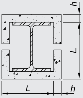
Figure description:
Subject: Structural cross-section of an encased steel I-beam.
Key Entities:
- Central I-beam: Steel structural member.
- Enclosure: Concrete or protective casing surrounding the I-beam.
Dimensional Variables:
- : Overall height and width of the outer assembly.
- : Thickness of the enclosure walls.
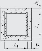
Figure description:
Subject: Cross-section diagram of a precast concrete column cover.
Key Components & Dimensions:
- Inner Core: Labeled with width and height .
- Concrete Cover: Outer layer surrounding the core, textured to represent concrete.
- Thickness Dimensions: indicates the horizontal cover thickness, and indicates the vertical cover thickness.
(a) Precast concrete column covers
(b) Concrete-encased HSS
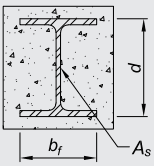
Figure description:
Entity: Concrete-encased wide-flange shape
- Components: Cross-section showing a steel wide-flange (I-beam shape embedded within a concrete block.
- Dimensional Variables:
- : Depth of the steel shape.
- : Width of the steel flange.
- : Cross-sectional area of the steel shape.
(c) Concrete-encased wide-flange shape
For wide-flange columns completely encased in concrete with all reentrant spaces filled, the thermal capacity of the concrete within the reentrant spaces is permitted to be added to the ambient thermal capacity of the steel column, as follows:
(A-4-29)
where
width of the column flange, in. (mm)
= depth of the column, in. (mm)
User Note: It is conservative to neglect this additional concrete term in the column fire-resistance calculation.
In the absence of more specific data for the ambient properties of the concrete encasement, it is permitted to use the values provided in Table A-4.3.2.
User Note: The estimated free moisture content of concrete given in Table A-4.3.2 may not be appropriate for all conditions, particularly for older concrete that has already been in service for a longer time. For these and similar situations of uncertainty, it is conservative to not rely on this beneficial effect of the free moisture and to assume the concrete is completely dry with for fire resistance of .
- (d) Noncomposite columns encased in masonry units of concrete or clay
The fire resistance of noncomposite columns protected by encasement with concrete masonry units or with clay masonry units is permitted to be determined from the following expression:
W 0.7 1.6 (As/dmTe) 0.8 R=0.17 + 0.285 1.0+42.7 (A-4-30) D Ko 0.2 (0.25p+T)
(A-4-30M)
where
- cross-sectional area of column, in.
- heated perimeter of column, in. (mm)
- thermal conductivity of concrete or clay masonry unit, Btu/hr-ft-°F (W/m-K) (see Table A-4.3.3)
- = fire-resistance rating of column assembly, hr
- equivalent thickness of concrete or clay masonry unit, in accordance with ACI 216.1, in. (mm)
weight of column,
- density of the concrete or clay masonry unit,
- = inner perimeter of concrete or clay masonry protection, in. (mm)
The thermal conductivity values given in Table A-4.3.3 as a function of the concrete or clay masonry unit density is permitted for use with this encasement protection formulation.
User Note: Equations A-4-30 and A-4-30M are derived from Equation A-4-27 assuming -°F (840 J/kg-K), , and . The following cross sections illustrate three different configurations for concrete masonry units or clay masonry unit encasement of steel columns, along with the applicable fire-protection design variables.
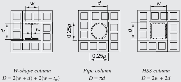
Figure description:
The image displays cross-sectional diagrams of masonry unit encasement for three types of steel columns with their respective design variables:
1. W-shape column
- Variables:
- : Width of the flange
- : Depth of the column
- : Thickness of the web
- Equation:
2. Pipe column
- Variables:
- : Outer diameter of the pipe
- : Distance labels indicating quadrant dimensions related to the perimeter
- Equation:
3. HSS (Hollow Structural Section column
- Variables:
- : Width of the section
- : Depth of the section
- Equation:
- = depth of a wide-flange column, outside diameter of pipe column, or outside dimension of hollow structural section column, in. (mm)
thickness of web of wide-flange column, in. (mm)
- width of flange of wide-flange or hollow structural section, in. (mm)
TABLE A-4.3.2 Ambient Properties of Concrete Encasement for Steel Column Fire Resistance
| Property | Normal Weight Concrete | Lightweight Concrete |
|---|---|---|
| Thermal conductivity, Kc | 0.95 Btu/hr-ft-°F (1.64 W/m-K) | 0.35 Btu/hr-ft-°F (0.61 W/m-K) |
| Specific heat, cc | 0.20 Btu/lb-°F (0.840 kJ/kg-K) | 0.20 Btu/lb-°F (0.840 kJ/kg-K) |
| Density, pc | 145 lb/ft3 (2 300 kg/m3) | 110 lb/ft3 (1 800 kg/m3) |
| Equilibrium (free) moisture content, m, by volume | 4% | 5% |
TABLE A-4.3.3 Thermal Conductivity of Masonry Units for Steel Column Encasement
| Unit Density, dm, lb/ft3 (kg/m3) | Unit Thermal Conductivity Kc, Btu/hr-ft-°F (W/m-K) |
|---|---|
| Concrete Masonry Units | |
| 80 (1 300) | 0.207 (0.36) |
| 85 (1 400) | 0.228 (0.40) |
| 90 (1 400) | 0.252 (0.44) |
| 95 (1 500) | 0.278 (0.48) |
| 100 (1 600) | 0.308 (0.53) |
| 105 (1 700) | 0.340 (0.59) |
| 110 (1 800) | 0.376 (0.65) |
| 115 (1 800) | 0.416 (0.72) |
| 120 (1 900) | 0.459 (0.80) |
| 125 (2 000) | 0.508 (0.88) |
| 130 (2 100) | 0.561 (0.97) |
| 135 (2 200) | 0.620 (1.1) |
| 140 (2 200) | 0.685 (1.2) |
| 145 (2 300) | 0.758 (1.3) |
| 150 (2 400) | 0.837 (1.5) |
| Clay Masonry Units | |
| 120 (1 900) | 1.25 (2.2) |
| 130 (2 100) | 2.25 (3.9) |
4.3.2b Composite Steel-Concrete Columns
The fire-resistance rating of columns acting compositely with concrete (filled or encased) is permitted to be based on the size of the composite member and concrete protection in accordance with this section.
- (a) Filled columns
The fire-resistance rating, , of hollow structural section (HSS) columns filled with unreinforced normal weight concrete, steel-fiber-reinforced normal weight concrete, or bar-reinforced normal weight concrete is permitted to be determined in accordance with Equation A-4-31 or A-4-31M:
(A-4-31)
(A-4-31M)
where
- compressive force due to unfactored dead load and live load, kips (kN)
- outside diameter for circular columns, in. (mm)
- = outside dimension for square columns, in. (mm)
- = least outside dimension for rectangular columns, in. (mm)
- column effective length, ft (mm)
- fire-resistance rating, hr
- constant determined from Table A-4.3.4
- -day compressive strength of concrete, ksi (MPa)
The application of Equations A-4-31 and A-4-31M shall be limited by all of the following conditions:
- (1) The required fire-resistance rating, R, shall be less than or equal to the limits specified in Tables A-4.3.5 or A-4.3.5M.
- (2) The specified compressive strength of concrete, , the column effective length, , the dimension , the concrete reinforcement ratio, and the thickness of the concrete cover shall be within the limits specified in Tables A-4.3.5 or A-4.3.5M.
- (3) C shall not exceed the design strength of the concrete or the reinforced concrete core determined in accordance with this Specification.
- (4) A minimum of two 1/2-in.- (13-mm-) diameter holes shall be placed opposite each other at the top and bottom of the column and at maximum 12 ft (3.7 m) on center spacing along the column height. Each set of vent holes should be rotated 90° relative to the adjacent set of holes to relieve steam pressure.
TABLE A-4.3.4 Values of Constant a for Normal Weight Concrete
| Aggregate Type | Concrete Fill Type | Reinforcement Ratio, % | a | |
|---|---|---|---|---|
| Circular Columns | Square or Rectangular Columns | |||
| siliceous | unreinforced | NA | 0.070 | 0.060 |
| siliceous | steel-fiber- reinforced | 2 | 0.075 | 0.065 |
| siliceous | steel-bar- reinforced | 1.5−3 | 0.080 | 0.070 |
| 3−5 | 0.085 | 0.070 | ||
| carbonate | unreinforced | NA | 0.080 | 0.070 |
| carbonate | steel-fiber- reinforced | 2 | 0.085 | 0.075 |
| carbonate | steel-bar- reinforced | 1.5−3 | 0.090 | 0.080 |
| 3−5 | 0.095 | 0.085 | ||
TABLE A-4.3.5 Limits for the Use of Equation A-4-31 Parameters
| Parameter | Concrete Fill Type | ||
|---|---|---|---|
| Unreinforced | Steel-Fiber- Reinforced | Steel-Bar- Reinforced | |
| R, hr | ≤ 2 | ≤ 3 | ≤ 3 |
| ′fc, ksi | 2.9−5.8 | 2.9−8.0 | 2.9−8.0 |
| Lc, ft | 6.5−13.0 | 6.5−15.0 | 6.5−15.0 |
| D (round), in. | 5.5−16.0 | 5.5−16.0 | 6.5−16.0 |
| D (square or rectangular), in. | 5.5−12.0 | 4.0−12.0 | 7.0−12.0 |
| Reinforcement, % | NA | 2% of concrete mix by mass | 1.5−5% of section area |
| Concrete cover, in. | NA | NA | ≥ 1.0 |
NA = not applicable
- (b) Composite columns encased in concrete
The fire resistance of composite columns fully encased within normal weight or lightweight concrete and with no unfilled spaces is permitted to be determined as the lesser of Equation A-4-30 or A-4-30M and the values in Table A-4.3.6.
TABLE A-4.3.5M Limits for the Use of Equation A-4-31M Parameters
| Parameter | Concrete Fill Type | ||
|---|---|---|---|
| Unreinforced | Steel-Fiber- Reinforced | Steel-Bar- Reinforced | |
| R, hrs | ≤ 2 | ≤ 3 | ≤ 3 |
| ′fc, MPa | 20−40 | 20−55 | 20−55 |
| Lc, mm | 2 000−4 000 | 2 000−4 500 | 2 000−4 500 |
| D (round), mm | 140−410 | 140−410 | 165−410 |
| D (square or rectangular), mm | 140−305 | 102−305 | 175−305 |
| Reinforcement, % | NA | 2% of concrete mix by mass | 1.5−5% of section area |
| Concrete cover (mm) | NA | NA | ≥ 25 |
| NA = not applicable | |||
TABLE A-4.3.6 Minimum Size and Concrete Cover Limits for Fire Resistance of Composite Steel Columns Encased in Concrete with No Unfilled Spaces
| Fire-Resistance Rating, hr | Minimum Concrete Cover, h, in. (mm) | Minimum Column Outside Dimension, in. (mm) |
|---|---|---|
| 1 | 1 (25) | 8 (200) |
| 2 | 2 (50) | 10 (250) |
| 3 | 2 (50) | 12 (300) |
| 4 | 2 (50) | 14 (350) |
4.3.2c Composite or Noncomposite Steel I-Shaped Beams and Girders
The fire-resistance ratings of composite or noncomposite beams and girders shall be based upon the size of the element and the type of protection provided in accordance with this section.
These procedures establish a basis for determining resistance of structural steel beams and girders that differ in size from that specified in approved fire-resistance-rated assemblies as a function of the thickness of fire-resistant material and the weight, , and heated perimeter, , of the beam or girder.
The beams provided in approved fire-resistance-rated assemblies shall be considered to be the minimum permissible size. Other beam or girder shapes are permitted to be substituted provided that the weight-to-heated-perimeter ratio, , of the substitute beam is equal to or greater than that of the minimum beam specified in the approved assembly.
The provisions in this section apply to beams and girders protected with sprayed or intumescent or mastic fire-resistant materials.
Larger or smaller composite or noncomposite beam and girder shapes protected with sprayed fire-resistant materials are permitted to be substituted for beams specified in approved unrestrained or restrained fire-resistance-rated assemblies, provided that the thickness of the fire-resistant material is adjusted in accordance with Equation A-4-32 or A-4-32M.
The use of these equations shall be limited by all of the following conditions:
- (a) The weight-to-heated-perimeter ratio for the substitute beam or girder, W D 1 1, shall be not less than 0.37 (U.S. customary units) or 0.022 (SI units).
- (b) The thickness of fire-protection materials calculated for the substitute beam or girder, , shall be not less than in. (10 mm).
- (c) The unrestrained or restrained beam rating shall be not less than 1 hour.
- (d) Where used to adjust the material thickness for a restrained beam, the use of this procedure is limited to sections classified as compact.
| h₂ = h₁[(W₁/D₁)+0.60] [(W₂/D₂)+0.60] | (A-4-32) |
| h₂ = h₁[(W₁/D₁)+0.036] [(W₂/D₂)+0.036] | (A-4-32M) |
where
heated perimeter of the beam, in. (mm)
weight of the beam or girder,
- = thickness of sprayed fire-resistant material, in. (mm)
Subscript 1 refers to the substitute beam or girder and the required thickness of fire-resistant material.
Subscript 2 refers to the beam and fire-resistant material thickness in the approved assembly.
User Note: This substitution equation based on for beams protected with spray-applied fire-resistive materials was developed by UL with the given limitations. The minimum ratio of 0.37 (0.022) prevents the use of this equation for determining the fire resistance of very small shapes that have not been tested. The in. (10 mm) minimum thickness of protection is a practical application limit based upon the most commonly used spray-applied fire protection materials.
The fire resistance of composite or noncomposite beams and girders protected with intumescent or mastic fire-resistant coatings shall be determined on the basis of standard fire-resistance-rated assemblies, and associated computations and limits as provided in the applicable rated assemblies.
4.3.2d Concrete-Encased Steel Beams and Girders
The fire-resistance rating of concrete-encased steel beams and girders is permitted to be determined in accordance with Item 2-1.1 or 2-1.2 of Table A-4.3.1.
4.3.2e Trusses
The fire resistance of trusses with members individually protected by fire-resistant materials applied onto each of the individual truss elements is permitted to be determined for each member in accordance with Appendix 4, Section 4.3.1. The protection thickness of truss elements that can be simultaneously exposed to fire on all sides shall be determined for the same weight-to-heated perimeter ratio, , as columns. The protection thickness of truss elements that directly support a floor or roof assembly is permitted to be determined for the same weight-to-heated-perimeter ratio, , as for beams and girders.
4.3.2f Concrete Floor Slabs on Steel Deck
For composite concrete floor slabs on trapezoidal steel decking wherein the upper width of the deck rib is equal to or greater than its bottom rib width, the fire-resistance rating, based on the thermal insulation criterion for the unexposed surface temperature, is permitted to be calculated using the following equation:
(A-4-33)
where
- fire-resistance rating, min
- concrete slab thickness above steel deck, in. (mm)
- depth of steel deck, in. (mm)
- largest upper width of deck rib, in. (mm)
- bottom width of deck rib, in. (mm)
- width of deck upper flange, in (mm)
- moisture content of the concrete slab, %. Range of applicability is between (0.0) and (0.1).
User Note: The slab dimensions in Equation A-4-33 are illustrated in the following figure.
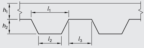
Figure description:
Slab Cross-Section Dimensions:
- : Thickness of the upper slab layer.
- : Height of the ribbed/corrugated section.
- : Top width of the rib opening.
- : Bottom width of the rib.
- : Top width of the section between ribs.
The coefficients to are given in Table A-4.3.7.
TABLE A-4.3.7 Coefficients a₀ to a₁₆ for Use with Equation A-4-33
| Coefficient | Coefficient Value | |
|---|---|---|
| Normal weight concrete | Lightweight concrete | |
| a0 | 38.6 min | 68.7 min |
| a1 | -5.08 min/in. (-0.2 min/mm) | -36.58 min/in. (-1.44 min/mm) |
| a2 | -1.45 min/in. (-0.057 min/mm) | -2.79 min/in. (-0.11 min/mm) |
| a3 | -3.30 min/in. (-0.13 min/mm) | -12.70 min/in. (-0.5 min/mm) |
| a4 | -2.08 min/in. (-0.082 min/mm) | 20.07 min/in. (0.79 min/mm) |
| a5 | -118.1 min | -784.2 min |
| a6 | 4.06 min/in.2 (0.0063 min/mm2) | 8.84 min/in.2 (0.014 min/mm2) |
| a7 | 1.48 min/in.2 (0.0023 min/mm2) | 3.61 min/in.2 (0.0056 min/mm2) |
| a8 | 1.87 min/in.2 (0.0029 min/mm2) | 3.68 min/in.2 (0.0057 min/mm2) |
| a9 | 0 | -2.39 min/in.2 (-0.0037 min/mm2) |
| a10 | 263.1 min/in. (10 min/mm) | 444.5 min/in. (18 min/mm) |
| a11 | 1.16 min/in.2 (0.0018 min/mm2) | 2.06 min/in.2 (0.0032 min/mm2) |
| a12 | 0 | -3.42 min/in.2 (-0.0053 min/mm2) |
| a13 | 0 | 91.44 min/in. (3.6 min/mm) |
| a14 | -0.65 min/in.2 (-0.001 min/mm2) | -0.97 min/in.2 (-0.0015 min/mm2) |
| a15 | 0 | 42.42 min/in. (1.67 min/mm) |
| a16 | 0 | -66.04 min/in. (-2.6 min/mm) |
User Note: If moisture content values are not available, can be used for normal weight concrete, and can be used for lightweight concrete, consistent with Annex D of Eurocode 4. Dry conditions ( ) will yield the most conservative fire-resistance rating.
4.3.2g Composite Plate Shear Walls
For unprotected composite plate shear walls meeting the requirements of Chapter I and satisfying the following conditions, the fire-resistance rating shall be determined in accordance with Equation A-4-34 or A-4-34M.
- (a) Wall slenderness ratio, , is less than or equal to 20
- (b) Axial load ratio, , is less than or equal to 0.2
- (c) Wall thickness, , is greater than or equal to 8 in. (200 mm)
(A-4-34)
(9.244) 0.24 Pu 230 1.91 sc R -18.5 +15 (A-4-34M) Pn 200
where R is the fire rating in hours, Pu is the required axial load in kips (N), and L, Pn, and tsc are as defined in Chapter I.
4.3.3 Restrained Construction
For floor and roof assemblies and individual beams in buildings, a restrained condition exists when the surrounding or supporting structure is capable of resisting forces and accommodating deformations caused by thermal expansion throughout the range of anticipated elevated temperatures. Cast-in-place or prefabricated concrete floor or roof construction secured to steel framing members, and individual steel beams and girders that are welded or bolted to integral framing members, shall be considered restrained construction.
4.3.4 Unrestrained Construction
Steel beams, girders, and frames that do not support a concrete slab shall be considered unrestrained unless the members are bolted or welded to surrounding construction that has been specifically designed and detailed to resist the effects of elevated temperatures.
A steel member bearing on a wall in a single span or at the end span of multiple spans shall be considered unrestrained unless the wall has been designed and detailed to resist the effects of thermal expansion.