C-6.16.1 general provisions
PDF page 700 · AISC 360-22
Winter (1958, 1960) developed the concept of a dual requirement for bracing design, which involves criteria for both strength and stiffness. Additional discussions are provided by Ziemian (2010). The design requirements of Appendix 6 are based upon this approach and consider two general types of bracing systems, panel and point, as depicted in Figure C-A-6.1. Prior to the 2016 edition of the Specification (AISC, 2016), the term relative bracing was used for panel bracing and nodal bracing was used for point bracing. The name change was made for clarity.
A panel-bracing system for a column is attached to two locations along the column length and may consist of systems such as diagonal bracing or shear diaphragms. The distance between these locations is the unbraced length, , of the column. The panel bracing system shown in Figure C-A-6.1(a) consists of the diagonals and struts that control the movement at one end of the unbraced length, point A, with respect to the other end of the unbraced length, point B. The forces in these bracing elements are resolved by forces in the beams and columns in the frame that is braced. The diagonal and strut both contribute to the strength and stiffness of the panel-bracing system. However, when the strut is a floor beam and the diagonal a brace, the floor beam stiffness is usually large compared to the stiffness of the brace and often can be ignored in the evaluation of the system stiffness. In such a case, the strength and stiffness of the bracing member and connection often controls the design of the panel-bracing system.
A point brace for a column limits movement only at the location it braces, and without direct interaction with adjacent braced points. The distance between adjacent braced points is the unbraced length, , of the column. The point-bracing system shown in Figure C-A-6.1(a) consists of a series of independent braces, which connect to a rigid abutment from the braced points including point C and point D. The forces in these bracing elements are resolved by other structural elements not part of the frame that is braced.
Figure C-A-6.1(b) demonstrates panel and point bracing systems that might be utilized in beams. Effective beam bracing is achieved by preventing either lateral movement of the compression flange or twist of the cross section; therefore, as depicted in Figure C-A-6.1(b), beam lateral bracing can be provided by either a panel-bracing system that consists of a system with diagonals, or point bracing such as a link to an external support (such as another lateral brace). Alternatively, effective beam bracing also can be provided by a point torsional brace such as a cross-frame torsional or other flexural member that frames between two adjacent beams. A torsional brace such as a cross-frame, cross-beam, diaphragm, bridging,
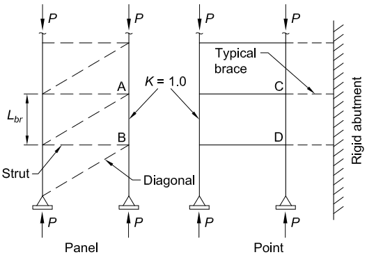
Figure description:
Key Information:
- Subject: Column bracing systems, specifically comparing "Panel" and "Point" configurations.
- Common Entities:
- : Vertical axial load applied to columns.
- : Effective length factor for the columns.
- : Unbraced length between support points.
- Panel Bracing (Left:
- Components: Includes horizontal Struts and Diagonal members between two vertical columns.
- Nodes: Specific points labeled A and B.
- Point Bracing (Right:
- Components: Consists of a Typical brace (horizontal link connecting columns to a Rigid abutment.)
- Nodes: Specific points labeled C and D.
(a) Column bracing
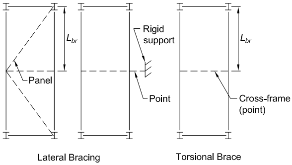
Figure description:
- Lateral Bracing:
- Panel Bracing: Diagonal dashed bracing forming a V-shape between vertical members.
- Point Bracing: Horizontal dashed line connected to a "Rigid support".
- Unbraced Length (: Distance between lateral brace points.
- Torsional Brace:
- Cross-frame (point: Horizontal dashed line connecting vertical members to provide torsional resistance.
- Unbraced Length (: Vertical distance between torsional brace points.
- Structural Members: Vertical lines with I-beam cross-sections at either end.
(b) Beam bracing
Fig. C-A-6.1. Types of bracing.
Specification for Structural Steel Buildings, August 1, 2022 AMERICAN INSTITUTE OF STEEL CONSTRUCTION
or girts/purlins combined with diagonal bracing between the beams restrains twist (not lateral displacement) of the beams at that particular location. With the required lateral and rotational restraint provided at the beam ends, the unbraced length, Lbr, in all of these cases is the distance from the support to the braced point.
The bracing requirements stipulated in Sections 6.2 and 6.3 allow for a member to develop a maximum load based on effective lengths, and , taken equal to the spacing between the brace points. The bracing requirements in Sections 6.2 and 6.3 generally are not sufficient to permit the development of member strengths based on or smaller than ; that is, the development of column or beam strengths based on a corresponding effective length factor of . Figure C-A-6.2 shows the critical buckling load versus the brace stiffness for an elastic cantilevered column with a brace of stiffness, , at its top. The ideal bracing stiffness for this column associated with ; that is, the bracing stiffness necessary to develop a column critical buckling load of , is . A brace having 5 times this stiffness is required for the column to reach a critical load of of based on . An infinitely stiff brace is required theoretically to reach .
In addition, the determination of bracing required to reach specified rotation capacities or ductility limits is beyond the scope of the Appendix 6 provisions.
Effective stability bracing must possess sufficient stiffness and strength. From a stiffness perspective, the respective provisions in Sections 6.2 and 6.3 for columns and beams stipulate a required brace stiffness, . Lateral bracing systems for columns and beams require at least twice the ideal stiffness while torsional bracing systems for beams require three times the ideal stiffness. The stiffness requirements include (LRFD) and (ASD). The required brace strength, , is a function of the initial out-of-alignment of the brace points (out-of-plumbness in the case of vertical columns), , and the brace stiffness, . The brace strength requirements are based on the nominal brace stiffness without the inclusion of and . Separate resistance and safety factors are applied in the design of the bracing system components to resist these forces.
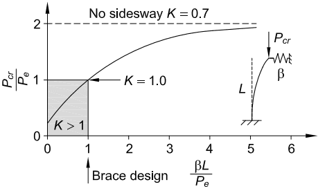
Figure description:
Buckling Load of a Braced Column
Effect of Brace Stiffness on Buckling Load
Annotations
- No sidesway K = 0.7 (horizontal_line - position: y = 2)
- K = 1.0 (text_label - position: x = 1, y = 1)
- K > 1 (shaded_area - position: x ∈ [0, 1, y ∈ [0, 1)
- Brace design (text_label - position: x = 1)
| 0.0 | 0.25 |
| 0.5 | 0.65 |
| 1.0 | 1.00 |
| 1.5 | 1.28 |
| 2.0 | 1.50 |
| 3.0 | 1.75 |
| 4.0 | 1.87 |
| 5.0 | 1.93 |
| 5.5 | 1.95 |
Notes: The chart illustrates the relationship between normalized buckling load (P_cr / P_e and non-dimensionalized brace stiffness (̢̢̢L / P_e. A schematic depicts a column of length L, fixed at the base, with a lateral spring of stiffness ̢̢̢ at the top where load P_cr is applied. The curve approaches an asymptote at y = 2, corresponding to the no-sidesway condition (K ≈ 0.7.)))
Fig. C-A-6.2. Cantilevered column with a variable stiffness brace at its top.
The impact of brace stiffness on deformations and brace forces shows the same general trends for different types of bracing (panel or point). As an example, Figure C-A-6.3 illustrates the impact of brace stiffness on deformations and brace forces necessary to brace the top of a simply supported column. In this case, the bracing at the column top can be either a panel or a point bracing system because both behave identically. Other types of bracing show similar behavior for both columns and beams. If the bracing stiffness, , is equal to the ideal brace stiffness for a perfectly plumb member, , the displacement of the bracing system becomes large as the critical buckling load is approached, in other words, as approaches , as illustrated in Figure C-A-6.3. Such large displacements would produce large
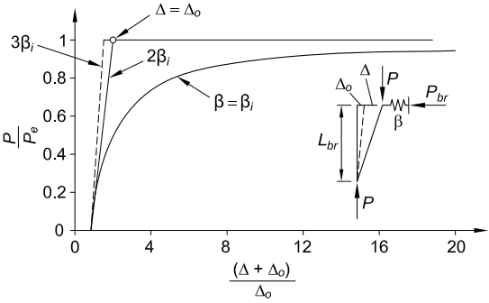
Figure description:
Bracing Stiffness and Column Strength
Relationship between Load Ratio and Displacement Ratio for Braced Columns
Legend
- β = βi — color: black; symbol: Solid curve
- 2βi — color: black; symbol: Solid line with corner at (2, 1
- 3βi — color: black; symbol: Dashed line with corner at (~1.67, 1
Annotations
- Δ = Δo (text_label - position: at ((Δ + Δo / Δo = 2, P / Pe = 1)))
| (Δ + Δo / Δo) | P / Pe (β = βi) | P / Pe (2βi) | P / Pe (3βi) |
|---|---|---|---|
| 1.0 | 0.0 | 0.0 | 0.0 |
| 1.33 | 0.25 | 0.33 | 0.5 |
| 1.5 | 0.33 | 0.5 | 0.75 |
| 1.67 | 0.4 | 0.67 | 1.0 |
| 2.0 | 0.5 | 1.0 | 1.0 |
| 4.0 | 0.75 | 1.0 | 1.0 |
| 6.0 | 0.83 | 1.0 | 1.0 |
| 8.0 | 0.88 | 1.0 | 1.0 |
| 12.0 | 0.92 | 1.0 | 1.0 |
| 16.0 | 0.94 | 1.0 | 1.0 |
| 20.0 | 0.95 | 1.0 | 1.0 |
Notes: The chart includes a schematic diagram of a braced column with height Lbr, initial displacement Δo, additional displacement Δ, axial load P, and bracing stiffness β producing a bracing force Pbr. The series 2βi and 3βi represent linear elastic behavior until they reach the Euler buckling load (P/Pe = 1, whereas β = βi represents the theoretical minimum required stiffness which approaches the buckling load asymptotically.)
(a) Column lateral deformations
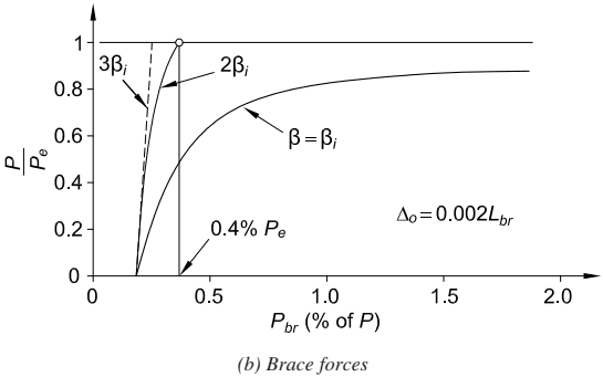
Figure description:
(b Brace forces
(b Brace forces
Legend
- — color: black; symbol: Solid line
- — color: black; symbol: Solid line
- — color: black; symbol: Dashed line
- Limit P/Pe = 1 — color: black; symbol: Solid horizontal line
Annotations
- (text_label - position: x = 1.6, y = 0.3)
- 0.4% Pe (text_label - position: x = 0.4, y = 0.1)
- Open circle marker (text_label - position: x = 0.4, y = 1.0)
- Limit line P/Pe = 1.0 (horizontal_line - position: y = 1.0)
- Vertical line at Pbr = 0.4 (vertical_line - position: x = 0.4)
| (% of ) | () | () | () | Limit |
|---|---|---|---|---|
| 0.2 | 0.00 | 0.00 | 0.00 | 1.00 |
| 0.25 | 0.18 | 0.35 | 0.80 | 1.00 |
| 0.27 | 0.24 | 0.45 | 1.00 | 1.00 |
| 0.3 | 0.35 | 0.65 | null | 1.00 |
| 0.4 | 0.50 | 1.00 | null | 1.00 |
| 0.5 | 0.60 | null | null | 1.00 |
| 0.75 | 0.75 | null | null | 1.00 |
| 1.0 | 0.82 | null | null | 1.00 |
| 1.5 | 0.88 | null | null | 1.00 |
| 2.0 | 0.91 | null | null | 1.00 |
Fig. C-A-6.3. Effect of stiffness of column point-bracing systems on (a) column lateral deformations and (b) brace forces.
bracing forces, and must be kept within reasonable tolerances for practical design. Providing a bracing system of twice the ideal stiffness for column bracing systems and beam bracing systems, with the exception torsional bracing systems, and 3 times the ideal stiffness for beam torsional bracing systems limits the deformation to a value approximately equal to the initial out-of-alignment between the brace points, , as the load approaches the critical buckling load corresponding to buckling between braced points, in other words, as approaches , as illustrated in Figure C-A-6.3. The resulting brace force is a linear function of the magnitude of the initial imperfection. For columns, the value that is often used for the initial out-of-alignment, , equals the initial out-of-plumbness provided in the AISC Code of Standard Practice for Steel Buildings and Bridges (AISC, 2022a).
In Figure C-A-6.3, for a brace stiffness of and the initial imperfection of , the resulting brace force, , for this point-bracing system is equal to of at . Similar results would be obtained for the shear brace force, , in a panel-bracing system. In the foregoing, is the distance between adjacent braced points as shown in Figure C-A-6.4, and is the relative lateral displacement of the braced points from the plumb (or aligned) position caused by erection tolerances, first-order effects from gravity and/or lateral loading on the structure, and first-order effects (i.e., the effects prior to amplification from member axial compression) from any other sources such as temperature movement, connection slip, etc.
As discussed in the user note in Chapter C, corresponds to an erection tolerance equal to maximum frame out-of-plumbness specified in the AISC Code of Standard Practice for Steel Buildings and Bridges. Similarly, for torsional bracing of beams, the important imperfection is an initial rotation, (Wang and Helwig, 2005), where is the distance between flange centroids. For other values of and , it is permissible to modify the bracing required strengths, , and , by direct proportion.
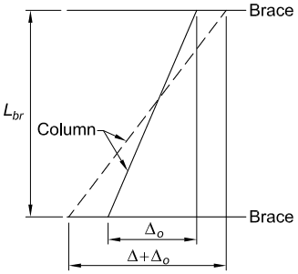
Figure description:
Subject: Fig. C-A-6.4, Definitions of initial displacements for panel and point braces.
Key Entities and Dimensions:
- Column: Represented by a dashed line for initial out-of-plumbness and a solid line for total displacement.
- Brace: Horizontal boundaries indicating support points at the top and bottom of the column segment.
- : The vertical distance or span between the horizontal braces.
- : Initial out-of-plumb displacement between the top and bottom of the column.
- : Total horizontal displacement, combining initial imperfection and additional movement.
Fig. C-A-6.4. Definitions of initial displacements for panel and point braces.
For bracing systems that restrain multiple columns, it is unlikely that all of the columns will be out-of-plumb in the same direction. For such cases, Chen and Tong (1994) recommend the use of an average initial displacement due to erection tolerances of , where is the number of columns, each with a random , stabilized by the bracing system. This reduced is added with the firstorder effects causing any additional out-of-plumbness or out-of-alignment between the brace points to determine the total force in the bracing system. In this situation, assuming a panel-bracing system, the total shear force in the bracing system can be calculated as
(C-A-6-1)
where
total relative displacement between the ends of the unbraced length under consideration due to erection tolerances, first-order effects of gravity and/or lateral loads on the structure, and first-order effects (i.e., the effects prior to amplification from member axial compression) from any other sources such as temperature movement, connection slip, etc., in. (mm)
In the absence of first-order forces in the bracing system, if the actual bracing stiffness provided (nominal stiffness with no stiffness reduction), , is larger than , the required brace strength, , in the case of a panel lateral brace, or in the case of a point lateral brace, can be multiplied by the following factor:
(C-A-6-2)
In the case of a panel-bracing system that contains a first-order shear force, this factor can be applied to the second term of Equation C-A-6-1, giving
(C-A-6-3)
By substituting the expression for from Equation A-6-2, one can show that Equation C-A-6-3 states that the total shear force in the panel-bracing system is equal to the first-order shear force plus a effect from the total vertical load being stabilized, , acting through the second-order relative end displacement of the panel (Griffis and White, 2013). The second term in the previously given equations for is based on the assumption of pins inserted in the column at each of the braced points, as in Winter's point bracing model (Winter, 1960). To account for the additional brace forces due to member curvature and member continuity across the braced points, the brace force, as defined by Equation A-6-1, is increased for point
bracing as explained later in Commentary Section 6.2. Prado and White (2015) and Lokhande and White (2015) observed that Equation C-A-6-2 tends to overestimate the reduction in the torsional brace strength requirement with increasing ; therefore, this equation is not recommended for application with torsional bracing.
Bracing systems often have multiple stiffness components that, combined, may impact the total brace stiffness. Many bracing systems behave as multiple springs in series. Potential components that can impact the stiffness of bracing systems are connections that may be flexible or can slip; therefore, the bracing system connections should be considered in the assessment of the bracing requirements. The connections and other components of the bracing system should be considered as components in series for the calculation of the bracing stiffness. Therefore, considering only bracing and its connections for point bracing, the actual bracing stiffness is tied to the connection and the brace stiffnesses by the relationship,
(C-A-6-4)
The resulting bracing system stiffness, , is less than the smaller of the connection stiffness, , and the brace stiffness, . Connection slip may be considered by increasing the value of used in the calculation of the bracing force requirements, as long as is small enough such that the brace is engaged well before the member reaches its maximum strength. Slip in connections with standard holes need not be considered, except when only a few bolts are used. This is in addition to the consideration of the fact that the initial or is unlikely to be the same in each of the members, via recommendations such as those by Chen and Tong (1994) discussed previously.
When evaluating the bracing of rows of columns or beams, consideration must be given to the accumulation of the bracing forces and flexibilities (Ziemian and Ziemian, 2017, 2021), which may result in different displacements at each column or beam location. In general, the bracing forces can be minimized by increasing the number of braced bays and using stiff braces.
In certain cases, it may be more effective to determne the bracing stiffness require ments as a multiple of the ideal bracing stiffness determined from a computational buckling analysis. For lateral bracing of columns and beams, the multiplier should be (LRFD) or (ASD), while for beam torsional bracing the multiplier should be (LRFD) or (ASD). Although this approach can be applied to any column, beam, or beam-column, specific cases of interest include members with brace spacings that vary significantly along the member length, members with stepped or tapered geometry, situations where it is desired to increase the bracing stiffness and/ or strength to satisfy high demands in one portion of a member but use lighter bracing in other regions, and partially braced members. The buckling analysis should account for the reduction in stiffness associated with the member elastic and inelastic strength limit states. Togay et al. (2015) summarize the stiffness reduction factors corresponding to limit states of Chapter E-column buckling, and Chapter F I -shaped member lateral-torsional buckling. For design by ASD. the buckling analysis
must be carried out under 1.6 times the ASD load combinations and the resulting ideal bracing stiffness values are then multiplied by to obtain the required bracing stiffnesses.