C-1.21.2 design by elastic analysis
PDF page 640 · AISC 360-22
In more traditional approaches, design for stability involves the combination of employing an analysis to determine the required strengths of components and the use of prescriptive code equations to proportion components so that they have adequate available strengths. Many traditional second-order analysis methods commonly available to designers account for and effects in flexure, but typically do not prove that equilibrium is satisfied on the deformed geometry of the system. They may also not account for twisting effects that can cause additional second-order effects that sometimes should be considered in design. The resulting effects of this approximation, such as neglecting twisting effects, have traditionally been accounted for when proportioning components and historically have been incorporated as part of the design requirements of Chapters D through K.
With more sophisticated analysis software being made available to designers, it is now possible to extend design methods, such as the direct analysis method, to provide engineers more opportunities to better approach complex design problems. Examples include, but are not limited to, defining the unbraced length of an arch or defining the effective length of an unbraced Vierendeel truss in which the axial force in the compression chord varies along its length.
A rigorous second-order elastic analysis, in which equilibrium and compatibility are satisfied on the deformed geometry of the system and its components, combined with adequate stiffness reductions for representing potential inelasticity, will indicate that deflections and internal force and moments will become unbounded as a structural system or any of its components approach instability. With instabilities, such as flexural buckling of compressive members now being monitored by the analysis,
the check for adequate design strength can be simplified to only needing to confirm adequate cross-section strength.
In this method of design, it is very important for a designer to establish that the analysis adequately captures all applicable second-order effects (including twist of the member, which can be important in some situations). Guidance is provided in this Commentary with a benchmark problem so that it will be clear that all significant second-order effects are being considered in order to use this method of design.
This new design approach is very useful in problems where it is not clearly evident what the unbraced lengths actually are for members in compression. Examples of such a situation occur when designing an arch structure for in-plane buckling effects under axial load, or when designing a through-truss (pony truss) where the top chord is continuous and seemingly unbraced out of plane. For these types of problems, the designer can perform a rigorous second-order elastic analysis as defined in this appendix and avoid a direct consideration of length effects for axially loaded compression members, while using the member cross-sectional strength in the appropriate limit state design equations. In such a case, buckling and instability are accounted for in producing additional second-order moments and shears caused by member twist.
1.2.1 General Stability Requirements
This section references the five requirements from Chapter C that make up a rigorous second-order elastic analysis. The requirements are similar to those contained in earlier Specification requirements defining a traditional second-order analysis that considered and effects in flexure. Since 2016, they have included the requirement to capture twisting and torsional effects that must be included as part of the design in some problems with long unbraced lengths that are subjected to additional internal forces caused by member twist. A rigorous second-order analysis can also capture the beneficial effects of member torsional strength due to warping restraint, for software that is written to include this component of member torsional strength, which adds to the member strength when a member is subjected to twisting effects. Software programs that do consider member twisting by providing for equilibrium on the deformed shape under each increment of loading, but do not consider the beneficial effects of torsional strength due to warping restraint (consideration of the member property), will provide a conservative solution to the member internal forces. The designer is cautioned to carefully examine the effects of twist and resulting second-order effects for each problem when using this method of analysis.
It is noted that this method is currently restricted to doubly symmetric sections, including I-shapes, HSS, and box sections, because current analytical testing has generally taken place with these section types. The designer can consider using singly symmetric shapes or other shapes as long as an investigation is undertaken to confirm that the results are properly capturing twisting effects (Liu et al., 2019) and generally produce designs comparable to the traditional design approach as specified in Chapter C and the other design requirements contained in Chapters D through K.
1.2.2 Calculation of Required Strengths
The details for the level of second-order analysis required for use of this design method are contained in this section. Traditional second-order analysis methods readily available to designers in most modern software, and commonly used in recent years, have traditionally only included flexural second-order effects defined by the and effects. These effects are explained in detail in Commentary Section C2. The difference between these traditional second-order analysis methods and the more rigorous second-order analysis referred to herein is the additional requirement for consideration of member twist, which results when an unbraced member is subjected to transverse load with or without axial load and containing an initial imperfection, such as camber or sweep, perpendicular to the plane of loading. Twist can also occur due to biaxial bending in a beam alone or in a beam-column with or without transverse loading that contains an out-of-plane imperfection.
Any analysis method that properly considers twist in a member due to an out-of-plane imperfection, or simply due to the tendency to twist under the effects of elastic or inelastic lateral-torsional buckling, will have additional moments caused by the twisting that must be resisted in the design. It has been found that twist becomes an important consideration in unbraced wide-flange sections as the unbraced length of the member approaches and as the ratio of strong-axis to weak-axis moment stiffness and strength increases. For such cases, the member capacity is reached with twist of the cross section in the range of 0.03 to 0.05 rad. Software that considers twisting effects using a large displacement analysis, where equilibrium is accounted for during each increment of loading in a line element member model, or software that contains additional degrees of freedom ( 14 degrees of freedom) in a line element member model that includes twisting and warping restraint effects, is able to pick up these additional second-order effects not customarily accounted for in traditional software using a 12-degree-of-freedom line element member model considering only and effects. While finite element models are able to pick up twisting and warping restraint effects and are readily available in some commercial software, they are not routinely used in a design office practice for most analyses.
Deformations to Be Considered in the Analysis. The requirements for exactly what imperfection deformations are to be modeled as part of the rigorous second-order analysis is left to the designer for each particular design case. Normally, the imperfection limits (camber, sweep, and twist) specified in the various ASTM Specifications for the member type would be consulted. Typically, for W-shape column members, an imperfection out-of-plane of 1/1,000 times the member's unbraced length would be used, unless a larger or smaller tolerance is justified by the fabrication. Generally, it is only necessary to consider the imperfection about the axis where buckling is likely to occur. It has been observed that the second-order internal forces in a member are incurred because of the natural tendency of the member to twist under loading, regardless of the imperfection used in the analysis. The important point is for some member perturbation to exist for the second-order effects to be picked up in the rigorous second-order analysis. For system imperfections caused by erection tolerances, the 1/500 out-of-plumbness, or a similar deviation in the nominal member end locations, should be included in the analysis unless justification exists
for the particular design case that warrants use of a different level of erection tolerance. Regardless of the imperfection chosen for the analysis, it is important for the designer to understand the sensitivity of the analysis results to the level of imperfection chosen. Past studies have shown that the second-order internal forces can be very sensitive to the magnitude of the imperfection chosen, especially in the case of member twist. Some analysis software may only consider the effects of member twist by using a large displacement algorithm that considers member equilibrium in the deformed shape produced by each applied load increment, but without any consideration of the beneficial effects of torsional strength from warping resistance of the cross section. Using the internal member force results from such an analysis is conservative.
If these additional second-order effects caused by member twist are accounted for in the structural analysis, it is possible to design the members for axial load using their cross-sectional strength, without consideration of flexural or flexural-torsional buckling of members caused by unbraced length effects.
Adjustments to Stiffness. Partial yielding accentuated by residual stresses in members can produce a general softening of the structure at the strength limit state that further creates destabilizing effects. The design method provided in this section is similar to the direct analysis method presented in Chapter C, and is also calibrated against distributed-plasticity analyses that account for the spread of yielding through the member cross section and along the member length. In these calibration studies, the residual stresses in W -shapes were assumed to have a maximum value of in compression at the flange tips, and a distribution matching the so-called Lehigh pattern-a linear variation across the flanges and uniform tension in the web (Ziemian, 2010).
Reduced stiffnesses, and , are used in the method provided in this section, just as it is for the direct analysis method of Chapter C. However, the stiffness reduction of 0.8 is also required for all other member properties, including and , to properly account for twisting effects in the analysis. The factor is similar to the inelastic stiffness reduction factor implied in the column curve to account for loss of stiffness under high compression loads when , and the 0.8 factor accounts for additional softening under combined axial compression and bending. It is a fortuitous coincidence that the reduction coefficients for both slender and stocky columns are close enough, such that the single reduction factor of works fairly well over the full range of slenderness. The use of reduced stiffness only pertains to analyses for strength and stability limit states. It does not apply to analyses for other stiffness-based conditions and criteria, such as for drift, deflection, vibration, and period determination.
For ease of application in design practice, where , the 0.8 reduction on , , and can be applied by modifying and by 0.8 in the analysis. However, for computer software that does semi-automated design, one should confirm that the reduced and are applied only for the second-order analysis. The elastic modulus should not be reduced in nominal strength equations that include for consideration of local buckling or slender-element effects.
Analysis Benchmark Problem. It is important for an engineer to understand the capabilities and limitations of the analysis software used in design. In order to provide a confidence level that a program is able to account for the second-order effects caused by the combination of axial force, flexure, and twist, it is strongly suggested that several benchmark problems be run to confirm the adequacy of the software being used. The following benchmark problem has been developed as one to consider in evaluating the accuracy of the analysis software required for application of the design method provided in Appendix 1, Section 1.2.
The results of an analysis procedure that does not consider member twist versus a procedure that does is demonstrated in Figure C-A-1.1. In this case, a member is subjected to loading that results in major-axis and minor-axis bending. As the figure indicates, a simply supported member with only ends restrained against twisting and simultaneously subjected to major-axis and minor-axis flexure will, in reality, twist to some extent. This twisting changes the magnitude of the components of major-axis and minor-axis moments when they are resolved to a coordinate system that references the cross-section axes of the deformed (twisted) state of the member.
Table C-A-1.1 provides numerical results at midspan for a W18x65 beam-column spanning 20 ft and subjected to four different combinations of loading. The axial and uniformly distributed loads are assumed factored and are applied proportionally.
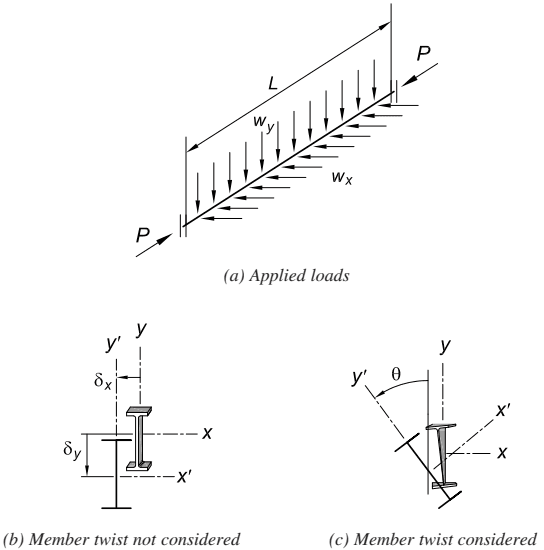
Figure description:
Structural diagram of a beam-column (W18×65 under various loading conditions.
Key Components:
- (a Applied Loads:
- Length member.
- Axial load applied at ends.
- Uniformly distributed vertical load .
- Uniformly distributed lateral load .
- (b Member Twist Not Considered: Cross-section midspan deflection showing translational displacements and along the principal axes.
- (c Member Twist Considered: Cross-section midspan deflection showing combined translation and rotational twist .
Fig. C-A-1.1. Deflection of cross section at midspan.
Specification for Structural Steel Buildings, August 1, 2022 AMERICAN INSTITUTE OF STEEL CONSTRUCTION
TABLE C-A-1.1 Results for Benchmark Problem Shown in Figure C-A-1.1
W18x65, L = 20 ft
| P, kips | 0 | 75 | 125 | 175 | |
|---|---|---|---|---|---|
| (wx = 0) wy, kip/ft | 4 | 3 | 2 | 1 | |
| Mux, ′ kip-in. | (a) | 2400 | 1833 | 1237 | 626 |
| (b) | 2386 | 1826 | 1235 | 624 | |
| (c) | 2399 | 1832 | 1237 | 626 | |
| Muy, ′ kip-in. | (a) | 0 | 0 | 0 | 0 |
| (b) | 258 | 234 | 192 | 309 | |
| (c) | 55.8 | 104 | 140 | 284 | |
| δy, in. | (a) | 0.580 | 0.443 | 0.299 | 0.151 |
| (b) | 0.694 | 0.524 | 0.342 | 0.201 | |
| (c) | 0.589 | 0.460 | 0.318 | 0.186 | |
| δx, in. | (a) | 0 | 0 | 0 | 0 |
| (b) | 0.967 | 0.951 | 0.833 | 1.397 | |
| (c) | 0.214 | 0.435 | 0.616 | 1.292 | |
| θ, rad | (a) | 0 | 0 | 0 | 0 |
| (b) | 0.1078 | 0.0790 | 0.0471 | 0.0358 | |
| (c) | 0.0233 | 0.0290 | 0.0266 | 0.0260 | |
| Equation H1-1 | (a) | 0.62 | 0.77 | 0.87 | 0.96 |
| (b) | 0.87 | 0.75 | 0.58 | 0.62 | |
| (c) | 0.68 | 0.62 | 0.53 | 0.60 |
(a) Analysis per Section C2.1; without member imperfection (b) Analysis per Appendix 1, Section 1.2; δox = L/1,000; ECw = 0 (c) Analysis per Appendix 1, Section 1.2; δox = L/1,000
The uniformly distributed load is applied in the vertical gravity direction throughout the loading history. The member is simply supported with rotation at the member ends restrained from twisting, with warping unrestrained. Therefore, the member ends are torsionally pinned (Seaburg and Carter, 1997). With a -factor equaling 1.0 , because the axial force in all combinations is less than 0.5 times the axial yield force, the stiffness reduction applied to all section properties, including , and , is 0.8 (or equivalently, the factor 0.8 could be applied to both and ). To provide some degree of transparency in the results, and because the length-to-height and length-to-width ratios of the member are approximately 13 and 32 , respectively, shear deformations have been assumed negligible and are therefore neglected. For each combination of loading, three sets of results are provided. In many commercial analysis software programs, the default setting for including shear deformations should be turned off when making comparisons with the tabulated results provided.
In Table C-A-1.1, rows labeled (a) provide analysis results from a traditional second-order analysis meeting the requirements of Section C2.1. In this case, a nominally straight member is assumed and only in-plane effects on flexure need be considered. With no out-of-plane behavior occurring, there is no resulting twist, out-of-plane deflection, or minor-axis bending moments. According to Section C3, the interaction of axial force and flexure is assessed by the requirements of Chapter H, in which the nominal compressive strength defined in Section E3 is based on an effective length equaling the unbraced length of the member.
Analysis results provided in rows (b) and (c) of Table C-A-1.1 correspond to the requirements of Appendix 1, Section 1.2. In these cases, an out-of-plane member imperfection in the shape of a sine curve with an amplitude of at midspan is included in the computational model. A more rigorous elastic analysis procedure is employed that establishes that equilibrium and compatibility are satisfied on the deformed shape of the member, and thereby includes second-order effects attributed to both and twist effects. Hence, the combination of the applied loads ( and ), initial out-of-plane imperfection ( ), and the resulting deflections and twist ( , and ) produce both major-axis and minor-axis bending moments, which at midspan are
(C-A-1-1)
(C-A-1-2)
In calculating the results given in row (b), the warping resistance of the section produced by cross-flange bending along the length of the member is neglected ( ) and torsional resistance is provided only by St. Venant stiffness ( ). Such warping resistance, as well as the St. Venant stiffness, is included in the analysis results provided in row (c).
The beneficial effects of including warping resistance are evident by significant reductions in deflections ( , and ) and minor-axis bending moments. Based on Appendix 1, Section 1.2.3, the interaction of axial force and flexure is assessed according to the requirements of Chapter H, in which the nominal compressive strength, , is taken as the cross-section compressive strength, , as defined in Section C2.3, and for this nonslender section is . In all cases, the nominal majoraxis and minor-axis flexural strengths are determined according to the provisions of Chapter F.
Analysis with Factored Loads. As with the direct analysis method presented in Chapter C and because of the high nonlinearity associated with second-order effects, it is essential that the analysis of the system be made with loads factored to the strength limit-state level. The Specification requirements for consideration of initial imperfections are intended to apply only to analyses for strength limit states. It is not necessary, in most cases, to consider initial imperfections in analyses for serviceability conditions such as drift, deflection, and vibration.
Where concrete shear walls or other nonsteel components contribute to the stability of the structure and the governing codes or standards for those elements specify a greater stiffness reduction, the greater reduction should be applied.
1.2.3 Calculation of Available Strengths
When the analysis meets the requirements of Appendix 1, Section 1.2.2, the member cross-sectional strength provisions for available strength in axially loaded members from Chapters D, E, and H can be used; otherwise, the provisions in Chapters F through K complete the process of design by this method. The effects of local buckling and reductions in member capacity because of slender elements of the member must still be considered for . The effective length factor, , and member buckling from length effects in axially loaded members in general need not be considered because they are directly accounted for in the structural analysis. The interaction of flexure and compression should be checked at all points along the member length, with the nominal flexural strengths, , determined from Chapter F.
It should be noted that the AASHTO Specification (AASHTO, 2014) addresses the consideration of flange lateral bending due to minor-axis bending moment, plus warping due to torsion, in the design of general curved and straight I-section members for flexure. White and Grubb (2005) provides an overview of the background to these equations. For beam-columns with significant flange bending due to twist, the minor-axis flexural capacity ratio for the flange subjected to the largest combined lateral bending due to overall minor-axis bending plus torsion may be used with Equation H1-1 as a conservative assessment. Aghayere and Vigil (2014) provide a straightforward discussion of this type of calculation with references to additional background research studies.
Where beams and columns rely upon braces for stability, they should generally be included as part of the lateral force-resisting system in the analysis. As long as imperfections are considered as specified, sufficient strength and stiffness to control member movement at the brace points can automatically be assessed.