C-1.31.3 design by inelastic analysis
PDF page 647 · AISC 360-22
This section contains provisions for the inelastic analysis and design of structural steel systems, including continuous beams, moment frames, braced frames, and combined systems. This appendix was modified in 2016 to allow for the use of a wider range of inelastic analysis methods, varying from the traditional plastic design approaches to the more advanced nonlinear finite element analysis methods. In several ways, this appendix represents a logical extension of the direct analysis method of Chapter C, in which second-order elastic analysis is used. The provision for moment redistribution in continuous beams, which is permitted for elastic analysis only, is provided in Appendix 8.
1.3.1 General Requirements
These requirements directly parallel the general requirements of Chapter C and are further discussed in Commentary Section C1.
Various levels of inelastic analysis are available to the designer (Ziemian, 2010; Chen and Toma, 1994). All are intended to account for the potential redistribution of member and connection forces and moments that are a result of localized yielding as a structural system reaches a strength limit state. At the higher levels, they have the ability to model complex forms of nonlinear behavior and detect member and frame instabilities well before the formation of a plastic mechanism. Many of the strength design equations in this Specification, for members subjected to compression, flexure, and combinations thereof, were developed using refined methods of inelastic analysis along with experimental results and engineering judgment (Yura et al., 1978; Kanchanalai and Lu, 1979; Bjorhovde, 1988; Ziemian, 2010). Also, the following research has provided significant advances in procedures for the direct application of second-order inelastic analysis in design: Ziemian et al. (1992); White and Chen (1993); Liew et al. (1993); Ziemian and Miller (1997); Chen and Kim (1997); and Surowek (2010). Correspondingly, there has been a steady increase in the inclusion of provisions for inelastic analysis in commercial steel design software, but the level varies widely. Use of any analysis software requires an understanding of the aspects of structural behavior it simulates, the quality of its methods, and whether or not the software’s ductility and analysis provisions are equivalent to those of Appendix 1, Sections 1.2 and 1.3. There are numerous studies available for verifying the accuracy of an inelastic analysis (Kanchanalai, 1977; El-Zanaty et al., 1980; White and Chen, 1993; Maleck and White, 2003; Martinez-Garcia and Ziemian, 2006; Ziemian, 2010).
With this background, it is the intent of this appendix to allow certain levels of inelastic analysis to be used in place of the Specification design equations as a basis for confirming the adequacy of a member or system. In all cases, the strength limit state behavior being addressed by the corresponding provisions of the Specification needs to be considered. For example, Section E3 provides equations that define the nominal compressive strength corresponding to the flexural buckling of members without slender elements. The strengths determined by these equations account for many factors, which primarily include the initial out-of-straightness of the compression member, residual stresses that result from the fabrication process, and the reduction of flexural stiffness due to second-order effects and partial yielding of the cross section. If these factors are directly incorporated within the inelastic analysis and a comparable or higher level of reliability can be confirmed, then the specific strength equations of Section E3 need not be evaluated. In other words, the inelastic analysis will indicate the limit state of flexural buckling and the design can be evaluated accordingly. On the other hand, suppose that the same inelastic analysis is not capable of modeling flexural-torsional buckling. In this case, the provisions of Section E4 would need to be evaluated. Other examples of strength limit states not detected by the analysis may include, but are not limited to, lateral-torsional buckling strength of flexural members, connection strength, and shear yielding or buckling strengths.
Item (e) of the General Requirements given in Appendix 1, Section 1.3.1, states that “uncertainty in system, member, and connection strength and stiffness” shall be taken into account. Member and connection reliability requirements are fulfilled by the probabilistically derived resistance factors and load factors of the load and resistance factor design method of this Specification. System reliability considerations are
still a project-by-project exercise and no overall methods have, as yet, been developed for steel building structures. Introduction to the topic of system reliability can be found in textbooks, for example, Ang and Tang (1984), Thoft-Christensen and Murotsu (1986), and Nowak and Collins (2000), as well as in many publications, for example, Buonopane and Schafer (2006).
Because this type of analysis is inherently conducted at ultimate load levels, the provisions of this appendix are limited to the design basis of Section B3.1 (LRFD).
In accordance with Section B3.8, the serviceability of the design should be assessed with specific requirements given in Chapter L. In satisfying these requirements in conjunction with a design method based on inelastic analysis, consideration should be given to the degree of steel yielding permitted at service loads. Of particular concern are (a) permanent deflections that may occur due to steel yielding, and (b) stiffness degradation due to yielding and whether this is modeled in the inelastic analysis.
Although the use of inelastic analysis has great potential in earthquake engineering, the specific provisions beyond the general requirements of this appendix do not apply to seismic design. The two primary reasons for this are as follows:
- (a) In defining "equivalent" static loads for use in elastic seismic design procedures, member yielding and inelastic force redistribution is already implied through the specification of seismic response modification factors (R-factors) that are greater than unity. Therefore, it would not be appropriate to use the equivalent seismic loads with a design approach based on inelastic analysis.
- (b) The ductility requirements for seismic design based on inelastic analysis are more stringent than those provided in this Specification for nonseismic loads.
Criteria and guidelines for the use of inelastic analysis and design for seismic applications are provided in Chapter 16 of the ASCE/SEI 7 (ASCE, 2022), ASCE/SEI 41 (ASCE, 2017), and Resource Paper 9, “Seismic Design Using Target Drift, Ductility, and Plastic Mechanism as Performance Criteria” in the NEHRP Recommended Seismic Provisions for New Buildings and Other Structures (FEMA, 2009). As described in these documents, when nonlinear (inelastic) static analysis is used for seismic design, the earthquake loading effects are typically quantified in terms of target displacements that are determined from ground motion spectral acceleration. Alternatively, for nonlinear (inelastic) dynamic analysis, the earthquake loading effects are defined in terms of input ground motions that are selected and scaled to match ground motion spectra. For the seismic design of new buildings, capacity design strategies are highly recommended to control the locations of inelastic action to well-defined mechanisms (FEMA, 2009; Deierlein et al., 2010).
Connections adjacent to plastic hinges must be designed with sufficient strength and ductility to sustain the forces and deformations imposed under the required loads. The practical implementation of this rule is that the applicable requirements of Section B3.4 and Chapter J must be strictly adhered to. These provisions for connection design have been developed from plasticity theory and verified by extensive testing, as discussed in ASCE (1971) and in many books and papers. Thus, the
connections that meet these provisions are inherently qualified for use in designing structures based on inelastic analysis.
Any method of design that is based on inelastic analysis and satisfies the given general requirements is permitted. These methods may include the use of nonlinear finite element analyses (Crisfield, 1991; Bathe, 1995) that are based on continuum elements to design a single structural component, such as a connection, or the use of second-order inelastic frame analyses (McGuire et al., 2000; Clarke et al., 1992) to design a structural system consisting of beams, columns, and connections.
Appendix 1, Sections 1.3.2 and 1.3.3, collectively define provisions that can be used to satisfy the ductility and analysis requirements of Appendix 1, Section 1.3.1. They provide the basis for an approved second-order inelastic frame analysis method. These provisions are not intended to preclude other approaches meeting the requirements of Appendix 1, Section 1.3.1.
1.3.2 Ductility Requirements
Because an inelastic analysis will provide for the redistribution of internal forces due to yielding of structural components such as members and connections, it is imperative that these components have adequate ductility and be capable of maintaining their design strength while accommodating inelastic deformation demands. Factors that affect the inelastic deformation capacity of components include the material properties, the slenderness of cross-sectional elements, and the unbraced length. There are two general methods for assuring adequate ductility: (1) limiting the aforementioned factors, and (2) making direct comparisons of the actual inelastic deformation demands with predefined values of inelastic deformation capacities. The former is provided in this appendix. It essentially decouples inelastic local buckling from inelastic lateral-torsional buckling. It has been part of the plastic design provisions for several previous editions of the Specification. Examples of the latter approach in which ductility demands are compared with defined capacities appear in Galambos (1968b), Kato (1990), Kemp (1996), Gioncu and Petcu (1997), FEMA 350 (FEMA, 2000), ASCE/SEI 41 (ASCE, 2017), and Ziemian (2010).
1.3.2a Material
Extensive past research on the plastic and inelastic behavior of continuous beams, rigid frames, and connections has amply demonstrated the suitability of steel with yield stress levels up to 65 ksi (450 MPa) (ASCE, 1971).
1.3.2b Cross Section
Design by inelastic analysis requires that, up to the peak of the structure’s loaddeflection curve, the moments at the plastic hinge locations remain at the level of the plastic moment, which itself should be reduced for the presence of axial force. This implies that the member must have sufficient inelastic rotation capacity to permit the redistribution of additional moments. Sections that are designated as compact in Section B4 have a minimum rotation capacity of approximately (see Figure C-A-1.2) and are suitable for developing plastic hinges. The limiting width-to-thickness ratio designated as in Table B4.1b, and designated as in this appendix, is the maximum slenderness ratio that will permit this rotation capacity to be achieved.
Further discussion of the antecedents of these provisions is given in Commentary Section B4.
The additional slenderness limits in Equations A-1-1 through A-1-4 apply to cases not covered in Table B4.1b. Equations A-1-1 and A-1-2, which define width-to-thickness ratio limits of webs of wide-flange sections, rectangular HSS, and box sections under combined flexure and compression, have been part of the plastic design requirements in the Specification since the 1969 edition (AISC, 1969) and are based on research documented in Plastic Design in Steel, a Guide and a Commentary (ASCE, 1971). The equations for the flanges of HSS and box sections (Equation A-1-3), and for round HSS sections (Equation A-1-4), are from the Load and Resistance Factor Design Specification for Steel Hollow Structural Sections (AISC, 2000a).
Limiting the slenderness of elements in a cross section so that there is ductility at plastic hinge locations is permissible only for doubly symmetric shapes. In general, single-angle, tee, and double-angle sections are not permitted for use in plastic design because the inelastic rotation capacity in the regions where the moment produces compression in an outstanding leg will typically not be sufficient.
1.3.2c Unbraced Length
The ductility of structural members with plastic hinges can be significantly reduced by the possibility of inelastic lateral-torsional buckling. In order to provide adequate rotation capacity, such members may need more closely spaced bracing than would be otherwise needed for design in accordance with elastic theory. Equations A-1-5 and A-1-7 define the maximum permitted unbraced length in the vicinity of plastic hinges for wide-flange shapes bent about their major axis, and for rectangular shapes and symmetric box-section beams, respectively. These equations are a modified version of those appearing in the 2005 AISC Specification (AISC, 2005b), which were based on research reported by Yura et al. (1978) and others. The intent of these equations is to establish a minimum rotation capacity, , where is defined as shown in Figure C-A-1.2.
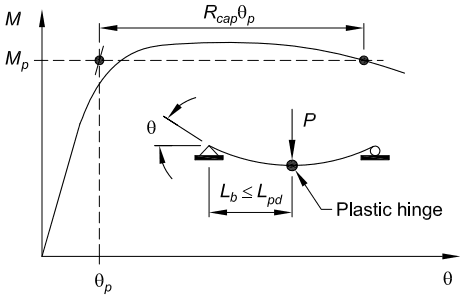
Figure description:
Moment-Rotation Curve with Inset Beam Model
Moment-Rotation (M-theta Relationship
Annotations
- M_p (horizontal_line - position: y = M_p)
- theta_p (vertical_line - position: x = theta_p)
- R_cap * theta_p (horizontal_range - position: Between x = theta_p and the second intersection of the curve with y = M_p)
- Plastic hinge (text_label - position: At the location of the point load P in the inset beam diagram)
- L_b <= L_pd (text_label - position: Distance between the left support and the plastic hinge in the inset diagram)
- P (text_label - position: Point load applied at the center of the beam in the inset diagram)
- theta (text_label - position: Angle of rotation at the beam support in the inset diagram)
| 0 | 0 |
| (point of reference on dashed lines) | |
| (second intersection with line) |
Notes: The figure illustrates the moment-rotation behavior of a structural beam, featuring an elastic range, a hardening region above the plastic moment Mp, and a post-peak degradation. The inset diagram shows a simply supported beam with a central point load P, indicating where the plastic hinge forms and defining the rotation theta and length Lb.
Fig. C-A-1.2. Definition of rotation capacity.
Specification for Structural Steel Buildings, August 1, 2022 AMERICAN INSTITUTE OF STEEL CONSTRUCTION
Equations A-1-5 and A-1-7 have been modified to account for nonlinear moment diagrams and for situations in which a plastic hinge does not develop at the brace location corresponding to the larger end moment. The moment in these equations is the larger moment at the end of the unbraced length, taken as positive in all cases. The moment is the moment at the opposite end of the unbraced length corresponding to an equivalent linear moment diagram that gives the same target rotation capacity. This equivalent linear moment diagram is defined as follows:
- (a) For cases in which the magnitude of the bending moment at any location within the unbraced length, , exceeds , the equivalent linear moment diagram is taken as a uniform moment diagram with a value equal to as illustrated in Figure C-A-1.3(a). Because the equivalent moment diagram is uniform, the appropriate value for can be obtained by using .
- (b) For cases in which the internal moment distribution along the unbraced length of the beam is indeed linear, or when a linear moment diagram between and the actual moment at the opposite end of the unbraced length gives a larger magnitude moment in the vicinity of as illustrated in Figure C-A-1.3(b), is taken as equal to the actual moment, .
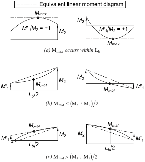
Figure description:
Fig. C-A-1.3. Equivalent linear moment diagram used to calculate
Legend:
- Dash-dot line: Equivalent linear moment diagram
Key Information & Cases:
- Case (a occurs within : When the maximum moment is between ends, the ratio . The equivalent diagram is a horizontal line at the level.
- Case (b : When the mid-span moment ( is less than or equal to the average of the end moments, the equivalent linear diagram directly connects the end moments and .
- Case (c : When the mid-span moment exceeds the average of the end moments, the equivalent linear diagram is a sloped line passing through at , defining new effective end moments and .
Key Entities:
- : Maximum moment within the braced length.
- : Moment at the center of the braced length (.
- : End moments of the equivalent linear diagram.
- : Braced length of the member.
Fig. C-A-1.3. Equivalent linear moment diagram used to calculate .
- (c) For all other cases in which the internal moment distribution along the unbraced length of the beam is nonlinear and a linear moment diagram between M2 and the actual moment, M1, underestimates the moment in the vicinity of M2, M1 is ′ defined as the opposite end moment for a line drawn between M2 and the moment at the middle of the unbraced length, Mmid, as illustrated in Figure C-A-1.3(c).
The moments and are individually taken as positive when they cause compression in the same flange as the moment , and negative, otherwise.
For conditions in which lateral-torsional buckling cannot occur, such as members with square and round compact cross sections and doubly symmetric compact sections subjected to minor-axis bending or sufficient tension, the ductility of the member is not a factor of the unbraced length.
1.3.2d Axial Force
The provision in this section restricts the axial force in a compression member to or approximately of the design yield load, . This provision is a cautionary limitation, because insufficient research has been conducted to confirm that sufficient inelastic rotation capacity remains in members subjected to high levels of axial force.
1.3.3 Analysis Requirements
For all structural systems with members subjected to axial force, the equations of equilibrium must be formulated on the geometry of the deformed structure. The use of second-order inelastic analysis to determine load effects on members and connections is discussed in the Guide to Stability Design Criteria for Metal Structures (Ziemian, 2010). Textbooks (Chen and Lui, 1991; Chen and Sohal, 1995; and McGuire et al., 2000) present basic approaches to inelastic analysis, as well as worked examples and computer software for detailed study of the subject.
Continuous and properly braced beams not subjected to axial loads can be designed by first-order inelastic analysis (traditional plastic analysis and design). First-order plastic analysis is treated in ASCE (1971), in steel design textbooks (Salmon et al., 2008), and in textbooks dedicated entirely to plastic design (Beedle, 1958; Horne and Morris, 1982; Bruneau et al., 2011; Wong, 2009). Tools for plastic analysis of continuous beams are readily available to the designer from these and other books that provide simple ways of calculating plastic mechanism loads. It is important to note that such methods use LRFD load combinations, either directly or implicitly, and, therefore, should be modified to include a reduction in the plastic moment capacity of all members by a factor of 0.9. First-order inelastic analysis may also be used in the design of continuous steel-concrete composite beams. Design limits and ductility criteria for both the positive and negative plastic moments are given by Oehlers and Bradford (1995).
1.3a Material Properties and Yield Criteria
This section provides an accepted method for including uncertainty in system, member, and connection strength and stiffness. The reduction in yield strength and member stiffness is equivalent to the reduction of member strength associated with
the AISC resistance factors used in elastic design. In particular, the factor of 0.9 is based on the member and component resistance factors of Chapters E and F, which are appropriate when the structural system is composed of a single member and in cases where the system resistance depends critically on the resistance of a single member. For systems where this is not the case, the use of such a factor is conserva- tive. The reduction in stiffness will contribute to larger deformations, and, in turn, increased second-order effects.
The inelastic behavior of most structural members is primarily the result of normal stresses in the direction of the longitudinal axis of the member equaling the yield strength of the material. Therefore, the normal stresses produced by the axial force and major- and minor-axis bending moments should be included in defining the plastic strength of member cross sections (Chen and Atsuta, 1976). Modeling of strain hardening that results in strengths greater than the plastic strength of the cross section is not permitted.
1.3b Geometric Imperfections
Because initial geometric imperfections may affect the nonlinear behavior of a structural system, it is imperative that they be included in the second-order analy- sis. Discussion on how frame out-of-plumbness may be modeled is provided in Commentary Section C2.2. Additional information is provided in ECCS (1984), Bridge and Bizzanelli (1997), Bridge (1998), and Ziemian (2010).
Member out-of-straightness should be included in situations in which it can have a significant impact on the inelastic behavior of the structural system. The significance of such effects is a function of (1) the relative magnitude of the member's applied axial force and bending moments, (2) whether the member is subjected to single or reverse curvature bending, and (3) the slenderness of the member.
In all cases, initial geometric imperfections should be modeled to represent the potential maximum destabilizing effects.
1.3c Residual Stresses and Partial Yielding Effects
Depending on the ratio of a member’s plastic section modulus, Z, to its elastic section modulus, S, the partial yielding that occurs before the formation of a plastic hinge may significantly reduce the flexural stiffness of the member. This is particularly the case for minor-axis bending of I-shapes. Any change to bending stiffness may result in force redistribution and increased second-order effects, and thus needs to be considered in the inelastic analysis.
The impact of partial yielding is further accentuated by the presence of thermal residual stresses, which are due to nonuniform cooling during the manufacturing and fabrication processes. Because the relative magnitude and distribution of these stresses is dependent on the process and the cross-section geometry of the member, it is not possible to specify a single idealized pattern for use in all levels of inelastic analysis. Residual stress distributions used for common hot-rolled doubly symmetric shapes are provided in the literature, including ECCS (1984) and Ziemian (2010). In most cases, the maximum compressive residual stress is 30 to of the yield stress.
The effects of partial yielding and residual stresses may either be included directly in inelastic distributed-plasticity analyses or by modifying plastic hinge based methods of analysis. An example of the latter is provided by Ziemian and McGuire (2002) and Ziemian et al. (2008), in which the flexural stiffnesses of members are reduced according to the amount of axial force and major- and minor-axis bending moments being resisted. This Specification permits the use of a similar strategy, which is provided in Section C2.3 and described in the Commentary to that section. If the residual stress effect is not included in the analysis and the provisions of Section C2.3 are employed, the stiffness reduction factor of 0.9 specified in Appendix 1, Section 1.3.3a (which accounts for uncertainty in strength and stiffness) must be changed to 0.8 . The reason for this is that the provisions given in Section C2.3 assume that the analysis does not account for partial yielding. Also, to avoid cases in which the use of Section C2.3 may be unconservative, it is further required that the yield or plastic hinge criterion used in the inelastic analysis be defined by the interaction Equations H1-1a and H1-1b. This condition on crosssection strength does not have to be met when the residual stress and partial yielding effects are accounted for in the analysis.