C-4.34.3 design by qualification testing
PDF page 685 · AISC 360-22
4.3.1 Qualification Standards
Qualification testing is an acceptable alternative to design by analysis for providing fire resistance. Fire-resistance ratings of building elements are generally determined
in accordance with procedures set forth in ASTM E119, Standard Test Methods for Fire Tests of Building Construction and Materials (ASTM, 2020d). Since its inception in 1917, the ASTM E119 standard has been the long-standing basis for the fire-resistance ratings of building construction in the United States for compliance with the conventional prescriptive requirements of the building code.
Tested building element designs, with their respective fire-resistance ratings, may be found in special directories and reports published by testing agencies. Additionally, calculation procedures based on standard test results may be used as specified in Standard Calculation Methods for Structural Fire Protection (ASCE, 2005), Chapter 7 of the International Building Code (ICC, 2018), and published literature. These ratings, expressed as a time duration, were intended to be developed from full-scale furnace testing of construction assemblies (floors, roofs, walls, beams, and columns) conducted in accordance with the ASTM E119 standard and subject to its one specified fire time-temperature exposure and acceptance criteria. AISC Design Guide 19, Fire Resistance of Structural Steel Framing (Ruddy et al., 2003), provides additional guidance and design examples on the subject.
For building elements that are required to prevent the spread of fire, such as walls, floors, and roofs, the test standard provides for measurement of the transmission of heat. For load-bearing building elements, such as columns, beams, floors, roofs, and load-bearing walls, the test standard also provides for measurement of the load-carrying ability under the standard fire exposure.
It is noted that rated assemblies directly reflect one particular construction subassembly, its protection materials, and specific configuration that had been successfully tested. Furthermore, the test assemblies are constrained by the minimum furnace and test frame dimensions mandated by ASTM E119, which often does not represent typical spans or member sizes used in building construction. In this regard, the
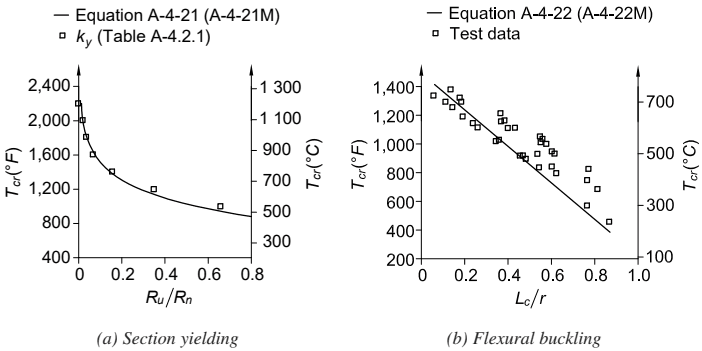
Figure description:
Comparison of Predicted and Experimental Critical Temperatures
(a Section yielding
Legend
- Equation A-4-21 (A-4-21M — color: black; symbol: Solid line
- k_y (Table A-4.2.1 — color: black; symbol: Open square
| Equation A-4-21 (A-4-21M)) | (Table A-4.2.1)) | |
|---|---|---|
| 0.00 | 2300 | 2200 |
| 0.02 | 1950 | 2000 |
| 0.04 | 1800 | 1810 |
| 0.08 | 1620 | 1610 |
| 0.16 | 1420 | 1400 |
| 0.20 | 1350 | null |
| 0.35 | 1150 | 1200 |
| 0.40 | 1100 | null |
| 0.60 | 970 | null |
| 0.65 | 950 | 1000 |
| 0.80 | 880 | null |
(b Flexural buckling
Legend
- Equation A-4-22 (A-4-22M — color: black; symbol: Solid line
- Test data — color: black; symbol: Open square
| Equation A-4-22 (A-4-22M)) | Test data) | |
|---|---|---|
| 0.05 | 1430 | 1350 |
| 0.08 | 1400 | null |
| 0.10 | 1370 | 1300 |
| 0.13 | 1330 | 1340 |
| 0.13 | null | 1380 |
| 0.15 | 1310 | 1260 |
| 0.18 | 1270 | 1320 |
| 0.18 | null | 1280 |
| 0.20 | 1240 | 1200 |
| 0.23 | 1200 | 1150 |
| 0.23 | null | 1120 |
| 0.25 | 1180 | 1150 |
| 0.25 | null | 1110 |
| 0.35 | 1040 | 1020 |
| 0.35 | null | 1040 |
| 0.37 | 1010 | 1160 |
| 0.37 | null | 1220 |
| 0.40 | 980 | 1120 |
| 0.40 | null | 1160 |
| 0.43 | 940 | 1110 |
| 0.45 | 910 | 920 |
| 0.45 | null | 930 |
| 0.48 | 870 | 900 |
| 0.48 | null | 930 |
| 0.55 | 780 | 840 |
| 0.55 | null | 1010 |
| 0.55 | null | 1040 |
| 0.55 | null | 1060 |
| 0.58 | 740 | 800 |
| 0.58 | null | 950 |
| 0.58 | null | 1010 |
| 0.60 | 710 | 850 |
| 0.60 | null | 940 |
| 0.60 | null | 950 |
| 0.62 | 680 | 800 |
| 0.76 | 510 | 580 |
| 0.76 | null | 750 |
| 0.76 | null | 830 |
| 0.81 | 450 | 690 |
| 0.86 | 390 | 460 |
| 0.88 | 370 | null |
Notes: The charts compare analytical equations with experimental or tabulated data for critical temperatures. Both charts feature dual Y-axes for temperature in Fahrenheit (left and Celsius (right. Values in the markdown table are estimated from the Fahrenheit scale.))
Fig. C-A-4.8. Critical temperature of steel members in yielding and flexural buckling (Sauca et al., 2021).
ASTM E119 Commentary states the following: “It is the intent that classifications shall register comparative performance to specific fire-test conditions during the period of exposure and shall not be construed as having determined suitability under other conditions or for use after the exposure.” The inventory of fire-resistance-rated assemblies, their components, and installation instructions have been catalogued by accredited laboratories, such as UL and Intertek, or other agencies, and maintained in databases for design reference by architects and engineers.
Over the many decades of standardized fire testing, various empirically based correlations of these data have been converted into equations and tabulations. These computational adaptations of fire-resistance-rated construction derived from ASTM E119 fire testing provide a convenient supplementary methodology for demonstrating code compliance that offers certain advantages over the sole reliance on the minimum requirements of individual rated assemblies. For example, a given assembly listing may indicate the minimum fire-protection thickness for a relatively small structural member. However, use of ancillary computations will commensurately reduce the required minimum protection thickness for larger members.
The primary source of accepted fire-resistance calculations for structural steel has been AISI and its ASTM E119 fire research conducted throughout the 1970s and 1980s. These industry-sponsored developments were originally captured in three AISI design guide publications (AISI, 1980, 1981, 1984), which were subsequently included in the preceding and current editions of Section 5 of SEI/ASCE/SFPE Standard 29, Standard Calculation Methods for Structural Fire Protection (ASCE, 2005) and in the U.S. model building codes. More recently, all of this information was summarized and well illustrated in AISC Design Guide 19. The standard fire protection and fire-resistance calculation methods for structural steel have now also been consistently transferred into the current National Fire Protection Association (NFPA) and International Code Council (ICC) model building codes.
The inclusion of provisions for fire-resistance calculations in this Specification was motivated by AISC’s and the steel industry’s interest in duly maintaining this important content and contributing to its future progress. In this manner, AISC desires to parallel the development of prescriptive fire-resistive criteria for the concrete, masonry, and timber industries that are embodied in separate standards authored by the respective committees.
Many of the archaic types of fire-resistant steel construction that were common in the 1900 to 1950 era, including fire-protection materials such as lath and plaster and clay tile, have been provided in Table C-A-4.3. A more general version of this table that included concrete, masonry, and wood framing has been provided in the current and past editions of the International Building Code (ICC, 2018). While this information may not be relevant to new construction, it is helpful to design professionals and code consultants during the life safety review and renovations of existing buildings. The principal reference for this archival information is “Fire Resistance Ratings of Beam, Girder and Truss Protections and Assemblies, Column Protections and Assemblies, Floor-Ceiling Assemblies, Roof-Ceiling Assemblies, Wall and Partition Assemblies” (American Insurance Association, 1964).
TABLE C-A-4.3 Minimum Fire Protection and Fire-Resistance Ratings of Archaic Steel Assemblies[a]
| Assembly | Item Number | Fire Protection Material Used | Minimum Thickness of Insulating Material for Fire-Resistance Times, in. (mm) | |||
|---|---|---|---|---|---|---|
| 4 hrs | 3 hrs | 2 hrs | 1 hr | |||
| 1. Steel columns and all of primary trusses | 1-3.1 | 4 in. (100 mm) hollow clay tile in two 2 in. (50 mm) layers; 1/2 in. (13 mm) mortar between tile and column; 3/8 in. (10 mm) metal mesh 0.046 in. (1.2 mm) wire diameter in horizontal joints; tile fill[b] | 4 (100) | – | – | – |
| 1-3.2 | 2 in. (50 mm) hollow clay tile; 3/4 in. (19 mm) mortar between tile and column; 3/8 in. (10 mm) metal mesh 0.046 in. (1.2 mm) wire diameter in horizontal joints; limestone concrete fill[b]; plastered with 3/4 in. (19 mm) gypsum plaster. | 3 (75) | – | – | – | |
| 1-3.3 | 2 in. (50 mm) hollow clay tile with outside wire ties 0.08 in. (2.0 mm) diameter at each course of tile or 3/8 in. (10 mm) metal mesh 0.046 in. (1.2 mm) diameter wire in horizontal joints; limestone or trap-rock concrete fill[b] extending 1 in. (25 mm) outside column on all sides. | – | – | 3 (75) | – | |
| 1-3.4 | 2 in. (50 mm) hollow clay tile with outside wire ties 0.08 in. (2 mm) diameter at each course of tile with or without concrete fill; 3/4 in. (19 mm) mortar between tile and column. | – | – | – | 2 (50) | |
| 1-8.1 | Wood-fibered gypsum plaster mixed 1:1 by weight, gypsum-to-sand aggregate applied over metal lath. Lath lapped 1 in. (25 mm) and tied 6 in. (150 mm) on center at all ends, edges, and spacers with 0.049 in. (1.2 mm) (No. 18 B.W. gage) steel tie wires. Lath applied over 1/2 in. (13 mm) spacers made of 3/4 in. (19 mm) furring channel with 2 in. (50 mm) legs bent around each corner. Spacers located 1 in. (25 mm) from top and bottom of member and a maximum of 40 in. (1 000 mm) on center and wire tied with a single strand of 0.049 in. (1.2 mm) (No. 18 B.W. gage) steel tie wires. Corner bead tied to the lath at 6 in. (150 mm) on center along each corner to provide plaster thickness. | – | – | 15/8 (41) | – | |
B.W. = Birmingham Wire
B.W. = Birmingham Wire [a]Generic fire-resistance ratings (those not designated as PROPRIETARY* in the listing) in GA-600 (Gypsum Association, 2021) are acceptable as if herein listed.
Association, 2021) are acceptable as if herein listed. [b]Reentrant parts of protected members to be filled solidly
Three other source reports of fire tests are as follows:
- • "Fire Tests of Building Columns," (Ingberg et al., 1921)
- • “Fire Resistance and Sound-Insulation Ratings for Walls, Partitions and Floors” (U.S. Department of Commerce, 1944)
- "Guidelines for Determining Fire Resistance Ratings of Building Elements" (BOCA, 1994).
Additional guidance on the subject of older construction may be found in “Fire Ratings of Archaic Materials and Assemblies” (HUD, 2000).
For beam, floor, and roof specimens tested under ASTM E119, two fire-resistance classifications—restrained and unrestrained—may be determined, depending on the conditions of restraint and the acceptance criteria applied to the specimen.
4.3.2 Structural Steel Assemblies
Structural steel beams and columns, and floor and roof assemblies for building construction have undergone extensive fire-resistance testing over the decades in conformance with the ASTM E119 standard. ASTM E119 requires that the test assembly or member be subjected to a prescribed fire exposure in a furnace, which is known as the so-called standard time-temperature exposure curve. The assembly may be fire-tested in combination with superimposed loading or without. The resultant fire-resistance rating is expressed as the number of hours that the assembly or element was able to withstand exposure to the standard fire before a limiting ASTM E119 criterion was reached.
One critical test limit for loaded assemblies defined in ASTM E119 is structural integrity, which is reflected by the member’s or assembly’s capability to support the applied load (the maximum design load, unless specified otherwise) without collapse. The second endpoint, or the only one if the fire test is performed without loading, is a limiting temperature of the steel during the standard fire exposure. For floor, wall, and roof construction, an additional ASTM E119 acceptance criterion for rating purposes is the maximum temperature rise on the unexposed surface of the specimen, or ignition of a cotton wool pad. This thermal endpoint demonstrates the separation or compartmentation function of a fire barrier that is intended to prevent hot spots or localized breaches of the barrier that would enable fire propagation to adjacent spaces or floors. The standard ASTM E119 test can thereby evaluate both the heat transmission characteristics and structural integrity of specimens under a single controlled fire exposure.
Higher material temperatures cause a degradation of mechanical properties that reduces structural load-bearing capability. Structural steel will lose about 50% of its ambient strength within the 1,000 to 1,200°F (540 to 650°C) temperature range. These limiting steel temperatures prescribed in ASTM E119 are approximately related to structural failure in the context that such elevated steel temperatures will deplete a substantial portion of the member’s typical design factor of safety or reserve strength. However, because structural instability depends on the governing limit state of the member, its stress and temperature distributions during the fire exposure, material overstrength, and other test assembly artifacts, the fire-resistance
TABLE C-A-4.4 ASTM E119 Temperature Endpoint Criteria
| Structural Assembly or Member | Temperature Location | Maximum Temperature, °F (°C) | Maximum Temperature Rise, °F (°C) |
|---|---|---|---|
| Walls and partitions, loaded or unloaded | Unexposed surface | NA | 250 (120) average and 325 (160) at any point |
| Steel columns or beams, unloaded | Steel section | 1,000 (540) average and 1,200 (650) at any point | NA |
| Column, loaded | NA | NA | NA |
| Loaded restrained floor and roof assemblies | Unexposed surface | NA | 250 (120) average and 325 (160) at any point |
| Loaded restrained floor and roof assemblies-steel beams or joists spaced at 4 ft (1.2 m) or less on center and steel deck | Steel section | 1,100 (590) | NA |
| Loaded restrained floor and roof assemblies-steel beams or joists spaced more than 4 ft (1.2 m) on center | Steel section | 1,000 (540) average and 1,200 (650) at any point | NA |
| Loaded unrestrained floor and roof assemblies | Unexposed surface | NA | 250 (120) average and 325 (160) at any point |
| Loaded unrestrained floor and roof assemblies-steel beams, joists, and deck | NA | NA | NA |
| Loaded unrestrained beam or joist | NA | NA | NA |
| NA = not applicable | |||
rating for a loaded assembly based on structural failure will typically exceed the rating developed only for the applicable steel temperature limit(s) specified in ASTM E119. Thus, the ASTM E119 steel temperature limits are regarded as conservative indexes of structural fire resistance for collapse prevention.
Table C-A-4.4 summarizes the pertinent temperature endpoint criteria in ASTM E119 for the various types of structural steel members and assemblies. It is noted that the unexposed surface limits are expressed as a temperature change from initial ambient conditions, while the remaining limiting steel temperatures are final values.
Most of the steel column fire-resistance ratings have been developed exclusively from unloaded member fire tests limited only by the ASTM E119 steel temperature criteria due to the furnace and facility constraints of U.S.-based laboratories. Laboratories have also been reluctant to approach an imminent collapse condition during testing, which could damage their furnace and related equipment. In general, and apart
from load-bearing walls, it is acknowledged that most steel fire-resistance-rated assemblies, their correlated and design methods, and other formulations presented in this appendix, were developed primarily in the temperature domain for the corresponding ASTM E119 limits; however, a number of beam, floor, and roof assembly ratings were also established on the basis of structural performance.
These procedures establish a basis for determining the fire-resistance rating of steel construction assemblies as a function of the thickness of fire-resistant material, the weight, , or area, , and the applicable heated perimeter, or , of the fire-protection material or structural steel member. The and ratios are equivalent and mutually convertible section properties that represent their thermal inertia. has conventionally been used for open wide-flange shapes, while has been used for closed hollow structural sections.
The heated perimeter, or , is a function of the configuration of the steel fire-protection material installation, which can be in either a contour or box profile, together with the nature of the heat exposure on the steel member. The latter is typically characterized as either an all-around exposure of the steel shape, as for an interior column, or as a three-sided exposure of a floor beam supporting a concrete floor. Tabulations of and values for these cases and for standard rolled wide-flange shapes are available from multiple sources, including AISC Design Guide 19, Fire Resistance of Structural Steel Framing (Ruddy et al., 2003), and other publications.
Several equations are included in Appendix 4, Section 4.3, for calculating the fire-resistance ratings of structural steel assemblies. Table C-A-4.5 provides the respective references for each equation.
4.3.2a Steel Columns
(b) Sprayed and intumescent/mastic fire-resistant materials
is a directly convertible and equivalent steel section property to , which has traditionally been used in fire-resistance computations for hollow structural sections (HSS). Similar to for open wide-flange shapes, tabulation of values for standard closed shapes with contour and box protection applications are available from multiple sources, including AISC Design Guide 19 and the published literature. The applicability limits of each given design correlation relative to the column assembly, sprayed fire-resistant protection product, , rating duration, minimum required thickness, and the like must be followed to remain within the range of the existing fire test result range.
4.3.2b Composite Steel-Concrete Columns
- (a) Filled columns
Concrete-filled HSS can effectively sustain load during a fire exposure without benefit of any external protection for the steel HSS. The concrete infill mass provides both an increased capacity for absorbing the heat caused by the fire and load-bearing strength to thereby extend the column fire-resistance duration. Research conducted at the National Research Council of Canada (Kodur and MacKinnon, 2000) has provided a basis for establishing an empirical equation
TABLE C-A-4.5 References for Equations in Appendix 4.3
| Equation | Reference |
|---|---|
| A-4-23 A-4-24 | Designing Fire Protection for Steel Columns, p. 5 (AISI, 1980) |
| A-4-25 | Designing Fire Protection for Steel Columns, p. 11 (AISI, 1980) |
| A-4-26 A-4-27 | Designing Fire Protection for Steel Columns, p. 17 (AISI, 1980) |
| A-4-28 | Designing Fire Protection for Steel Columns, p. 18 (AISI, 1980) |
| A-4-29 | “Fire Endurance of Concrete-Protected Steel Columns,” p. 30 (Lie and Harmathy, 1974) |
| A-4-30 | “Calculation of the Fire Resistance of Steel Hollow Structural Section Columns Filled With Plain Concrete,” p. 384 (Lie and Stringer, 1994) “Fire Performance of Concrete-Filled Hollow Steel Columns,” p. 93 (Kodur and Lie, 1995) |
| A-4-31 | “Fire Test of Loaded Restrained Beams Protected by Cementitious Mixture,” p. T1-11 (UL, 1984) |
to predict the standard fire resistance of filled round and square HSS for com- monly used story heights and steel sections. This empirical equation was derived from and can only be used within the allowable range of design variables, as given, and is not applicable to lightweight concrete infill.
The fire performance of a filled HSS column is improved when heat absorption occurs as the moisture in the concrete is converted to steam. The heat absorbed during this phase change is significant; however, the resulting steam must be released to prevent the adverse effects of an internal pressure build-up within the HSS column. Thus, vent holes must be provided in the steel section, as indicated in the given limitation (4).
- (b) Composite columns encased in concrete
The fire-resistance ratings and requirements in Table A-4.3.6 were directly adapted from the ACI 216.1 (ACI, 2014) provisions for conventional steel bar-reinforced concrete columns. Substitution of an embedded structural steel shape for steel bar reinforcement should not reduce the fire resistance of the load-bearing concrete parts of a column, and the fire-resistance rating, , computed for the same, but the assumed noncomposite steel column, accordingly verifies the fire resistance of the load-bearing steel shape. The concrete cover, , is defined as identical to that used for noncomposite steel columns encased in concrete.
4.3.2c Composite or Noncomposite Steel I-Shaped Beams and Girders
In the past, the substitution of larger beams for the minimum required sizes has been permitted based upon the thickness of web and flange elements, ratio, or the beam size designation. Extensive fire research has shown that the heat transfer to a protected steel beam or girder is actually a direct function of the ratio. As
a result, beam substitutions should be more directly based upon ratios. The significance of the thickness of web and flange elements and beam size is inherently included in the determination of ratios.
It is acceptable and conservative to protect a larger steel beam or girder that has a greater value than the of the minimum member size specified in an approved assembly with the thickness of fire protection material required for the minimum member size.
In the application of the so-called member substitution equation for sprayed fire-resistance materials, reference to a selected fire-resistance-rated assembly, for the designated protection product and rating time required for the project, is necessary to identify the benchmark fire-protection thickness and accompanying value of the steel shape in the rated assembly. The origins and example usage of this approach may be found in AISI (1984). Equation A-4-32 is the result of an analysis of data from nine restrained beam specimens tested in accordance with ASTM E119 Standard UL 263 (ASTM, 2020d). The analysis is contained in UL Report NC505-11 (UL, 1984). Additional background and examples for this are provided in AISC Design Guide 19. This general equation is only applicable to sprayed fire-resistance materials and not to intumescent or mastic coatings.
Adjustments to the fire resistance and protection thickness of beams and girders protected with intumescent or mastic fire-resistant coatings are allowed based on the particular selected coating product and a standard fire-resistance-rated assembly in which it is listed.
4.3.2e Trusses
For trusses, application of the column fire-resistance equation is more technically correct than the beam equation, because truss members are predominantly axially loaded and will require larger protection thicknesses than beams. Also, most truss elements can be exposed to fire on all four sides simultaneously. As a result, the heated perimeter and protection thickness of most truss members should be determined in the same manner as for columns. However, an exception is included for top chord elements that directly support floor or roof construction. The heated perimeter and protection thickness of such elements may be determined in the same manner as for beams and girders, or they may be conservatively determined in the same manner as for columns.
Additional guidance and examples for structural steel truss fire protection may be found in AISI (1981) and in AISC Design Guide 19.
4.3.2f Concrete Floor Slabs on Steel Deck
The development of Equation A-4-33 for composite slabs with trapezoidal steel decking is described in Jiang et al. (2019). This equation is based on the thermal insulation criterion, which is specified as the time required for an average temperature rise of 284°F (140°C) or a maximum temperature rise of 356°F (180°C), whichever governs, to be reached at the unexposed surface of the slab when the slab is subjected to a standard fire from below. For this application, the steel deck is limited to trapezoidal profiles wherein the upper width of the deck rib is greater than or equal
to the bottom width of the deck rib. Equation A-4-33 is not intended to be used for corrugated deck panels. The equation is based on finite element analysis of composite slabs with different geometries exposed to the standard ASTM E119 fire. The finite element analyses were validated against experimental data from composite slabs tested under ASTM E119 fires. Jiang et al. (2019) show that the equation presents an improvement over the method provided in Annex D of Eurocode 4 (CEN, 2005d). Note that in practice, it is generally not possible to determine the actual value of the moisture content of concrete a priori, and even if that were possible, the moisture content could change during the service life of the structure. A moisture content of for normal weight concrete and for lightweight concrete can be used, consistent with CEN (2005d). For more conservative fire rating estimates, dry condition, may be used. Note that in addition to the thermal insulation criterion, Annex D of Eurocode 4 (CEN, 2005d) provides additional structural capacity criteria based on the calculation of the sagging and hogging moment resistance of the composite slab that can be used for estimating the capacity at elevated temperatures.
Equation A-4-33 is based on a thermal conductivity coefficient for concrete consistent with the upper limit assumed in the development of the Eurocode 4 provisions and should provide conservative estimates of fire ratings for composite slabs with siliceous or carbonate aggregates.
4.3.2g Composite Plate Shear Walls
Equation A-4-34 for determining the fire-resistance rating of composite plate shear walls is based on research conducted by Anvari et al. (2020b). The equation provides conservative failure times for walls subjected to standard ISO or ASTM fire scenarios. The equations are based on data obtained from experiments and benchmarked numerical models. The equation can be used for composite plate shear walls that meet the detailing and design requirements of Specification Chapter I, namely the steel plate slenderness and tie spacing requirements. The limits for applicability of Equation A-4-34 are based on the range of parameters considered in the study. For walls with slenderness greater than 20, one-sided fire scenarios may start controlling the failure of the wall and additional fire protection may need to be provided. Typical axial load ratios for composite plate shear walls are in the range of 10 to 20%.
4.3.3 Restrained Construction
The ASTM E119 standard provides for tests of loaded beam specimens in the restrained condition, where the two ends of the beam specimen (including slab ends for composite steel-concrete beam specimens) are placed tightly against the test frame that supports the beam specimen; therefore, during fire exposure, the thermal expansion and rotation of the beam specimen ends are resisted by the test frame. A similar restrained condition is provided in the ASTM E119 tests on restrained loaded floor or roof assemblies, where the entire perimeter of the assembly is placed tightly against the test frame.
The practice of testing restrained specimens dates back to the early fire tests over 100 years ago, and it is predominant today in the qualification of structural steel framed and reinforced concrete floors, roofs, and beams in North America. While the current ASTM E119 standard does provide for an option to test loaded beam specimens and
loaded floor and roof assemblies in the unrestrained condition, this testing option is rarely used for structural steel and concrete. However, unrestrained loaded floor and roof specimens, with sufficient space around the perimeter to allow for free thermal expansion and rotation, are common in the tests of wood and cold formed steel-framed assemblies.
Gewain and Troup (2001) provide a detailed review of the background research and practices in the qualification fire-resistance testing and rating of structural steel and composite steel/concrete girders, beams, and steel-framed floors and roofs. The restrained assembly fire-resistance ratings, developed from tests on loaded restrained floor or roof specimens, and the restrained beam fire-resistance ratings, developed from tests on loaded restrained beam specimens, are commonly applicable to all types of steel-framed floors, roofs, girders, and beams, with minor exceptions, as recommended in Table X3.1 of ASTM E119, especially where they incorporate or support cast-in-place or prefabricated concrete slabs. AISC Design Guide 19, Fire Resistance of Structural Steel Framing (Ruddy et al., 2003), provides several detailed examples of steel-framed floor and roof designs by qualification testing.
4.3.4 Unrestrained Construction
An unrestrained condition is one in which thermal expansion at the support of load-carrying elements is not resisted by forces external to the element, and the supported ends are free to expand and rotate.
However, in the common practice for structural steel and composite steel-concrete beams and girders, the unrestrained beam ratings are developed from ASTM E119 tests on loaded restrained beam specimens or from ASTM E119 tests on loaded restrained floor or roof specimens, based only on temperature measurements on the surface of structural steel members. For steel-framed floors and roofs, the unrestrained assembly ratings are developed from ASTM E119 tests on loaded restrained floor and roof specimens, based only on temperature measurements on the surface of the steel deck, if any, and on the surface of structural steel members. As such, the unrestrained fire-resistance ratings are temperature-based ratings indicative of the time when the steel reaches specified temperature limits. These unrestrained ratings do not bear much direct relevance to the unrestrained condition or the load-bearing functions of the specimens in fire tests.
Nevertheless, unrestrained ratings provide useful supplementary information, and they are used as a conservative estimate of fire resistance in lieu of the restrained ratings in cases where the surrounding or supporting construction cannot be expected to accommodate the thermal expansion of steel beams or girders. For instance, as recommended in ASTM E119, Table X3.1, a steel member bearing on a wall in a single span, or at the end span of multiple spans, should be considered unrestrained when the wall has not been designed and detailed to resist thermal thrust.