C-8.18.1 approximate second-order elastic analysis
PDF page 727 · AISC 360-22
Section C2.1(b) states that a second-order analysis that captures both and effects is required. As an alternative to a more rigorous second-order elastic analysis, the amplification and summation of first-order elastic analysis forces and moments by the approximate procedure in this appendix is permitted. The main approximation in this technique is that it evaluates and effects separately, through separate multipliers, and , respectively, considering the influence of effects on the overall response of the structure (which, in turn, influences ) only indirectly, through the factor . A more rigorous second-order elastic analysis is recommended for accurate determination of the frame internal forces when is larger than 1.2 in members that have a significant effect on the response of the overall structure.
This procedure uses a first-order elastic analysis with amplification factors that are applied to the first-order forces and moments to obtain an estimate of the second-order forces and moments. In the general case, a member may have first-order load effects not associated with sidesway that are multiplied by the factor , and first-order load effects produced by sidesway that are multiplied by the factor . The factor estimates the effects on the nonsway moments in compression members. The factor estimates the effects on the forces and moments in all members. These effects are shown graphically in Figures C-C2.1 and C-A-8.1.
The factor applies only to internal forces associated with sidesway and is calculated for an entire story. In building frames designed to limit to a predetermined value, the factor may be found in advance of designing individual members by using the target maximum limit on within Equation A-8-7. Drift limits may also be set for design of various categories of buildings so that the effect of secondary bending is reduced (ATC, 1978; Kanchanalai and Lu, 1979). However, drift limits alone are not sufficient to allow stability effects to be neglected (LeMessurier, 1977).
In determining and the second-order effects on the lateral force-resisting system, it is important that include not only the interstory displacement in the plane of the lateral force-resisting system, but also any additional displacement in the floor or roof diaphragm or horizontal framing system that may increase the overturning effect of columns attached to and "leaning" against the horizontal system. Either the maximum displacement or a weighted average displacement, weighted in proportion to column load, should be considered.
The Specification provides only one equation, Equation A-8-7, for determining the elastic bucking strength of a story. This formula is based on the lateral stiffness of the story as determined from a first-order analysis and is applicable to all buildings. The 2005 AISC Specification (AISC, 2005b) offered a second formula based on the lateral buckling strength of individual columns, applicable only to buildings in which lateral stiffness is provided entirely by moment frames; that equation is
(C-A-8-1)
where
elastic buckling strength of the story, kips (N)
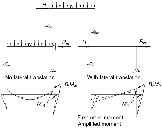
Figure description:
Fig. C-A-8.1. Moment amplification
Key Entities and Information:
- Structural Frame Scenarios:
- No lateral translation: Frame under gravity load ( with lateral movement prevented (reaction .
- With lateral translation: Frame under lateral load ( and force allowing for sway.
- Moment Components:
- : First-order moment for the no-translation case.
- : First-order moment for the lateral translation case.
- : Amplification factors for no-translation and lateral translation cases, respectively.
- Legend:
- Dashed line (---: First-order moment.
- Solid line (—: Amplified moment (second-order effects.
- Key Variables:
- : Lateral load.
- : Distributed gravity load.
- : Translation-related force/reaction.
- : Elastic buckling strength of the story.
Fig. C-A-8.1. Moment amplification.
Specification for Structural Steel Buildings, August 1, 2022 AMERICAN INSTITUTE OF STEEL CONSTRUCTION
This equation for the story elastic buckling strength was eliminated from the 2010 AISC Specification (AISC, 2010) because of its limited applicability, the difficulty involved in calculating correctly, and the greater ease of application of the story stiffness-based formula. Additionally, with the deletion of this equation, the expression was changed to because the story buckling strength is not the summation of the strengths of individual columns, as implied by the earlier symbol.
First-order member forces and moments with the structure restrained against sidesway are labeled and ; the first-order effects of lateral translation are labeled and . For structures where gravity load causes negligible lateral translation, and are the effects of gravity load and and are the effects of lateral load. In the general case, and are the results of an analysis with the structure restrained against sidesway; and are from an analysis with the lateral reactions from the first analysis (as used to find and ) applied as lateral loads. Algebraic addition of the two sets of forces and moments after application of multipliers and , as specified in Equations A-8-1 and A-8-2, gives reasonably accurate values of the overall second-order forces and moments.
The multiplier is applicable to forces and moments and in all members, including beams, columns, bracing diagonals, and shear walls, that participate in resisting lateral load. and will be zero in members that do not participate in resisting lateral load; hence, will have no effect on them. The multiplier is applicable only to compression members.
If for a particular direction of translation does not vary significantly among the stories of a building, it will be convenient to use the maximum value for all stories, leading to just two values, one for each direction, for the entire building. Where does vary significantly between stories, the multiplier for beams between stories should be the larger value.
When first-order end moments in columns are magnified by and factors, equilibrium requires that they be balanced by moments in the beams that connect to them as illustrated in Figure C-A-8.1. The multiplier does not cause any difficulty in this regard because it is applied to all members. The multiplier, however, is applied only to compression members. The associated second-order internal moments in the connected members can be accounted for by amplifying the moments in those members by the value of the compression member using the largest value, if there are two or more compression members at the joint. Alternatively, the difference between the magnified moment, considering only, and the first-order moment in the compression member(s) at a given joint may be distributed to any other moment-resisting members attached to the compression member(s) in proportion to the relative stiffness of those members. Minor imbalances may be neglected, based upon engineering judgment. Complex conditions may be treated more expediently with a more rigorous second-order analysis.
In braced frames and moment frames, is governed by the maximum slenderness ratio regardless of the plane of bending, if the member is subjected to significant biaxial bending, or the provisions in Section H1.3 are not utilized. Section H1.3 is an alternative approach for checking beam-column strength that provides for the
separate checking of beam-column in-plane and out-of-plane stability in members predominantly subjected to bending within the plane of the frame. However, expressed by Equation A-8-5 is always calculated using the slenderness ratio in the plane of bending. Thus, when flexure in a beam-column is about the major axis only, two different values of slenderness ratio may be involved in the amplified first-order elastic analysis and strength check calculations.
The factor in Equation A-8-7 accounts for the influence of effects on sidesway amplification. can be taken as 0.85 as a lower-bound value for stories that include moment frames (LeMessurier, 1977); if there are no moment frames in the story. Equation A-8-8 can be used for greater precision between these extreme values.
Second-order internal forces from separate structural analyses cannot normally be combined by superposition because second-order amplification is a nonlinear effect based on the total axial forces within the structure; therefore, a separate analysis must be conducted for each load combination considered in the design. However, in the amplified first-order elastic analysis procedure of Section 8.1, the first-order internal forces, calculated prior to amplification, may be superimposed to determine the total first-order internal forces.
Equivalent Uniform Moment Factor, , and Effective Length Factor, K. Equations A-8-3 and A-8-4 are used to approximate the maximum second-order moments in compression members with no relative joint translation and no transverse loads between the ends of the member. Figure C-A-8.2 compares the approximation for
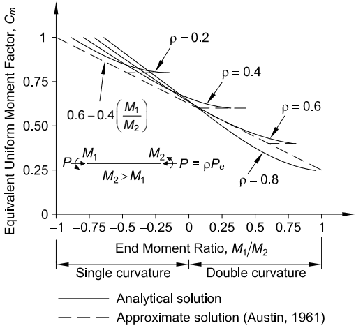
Figure description:
Comparison of Analytical and Approximate Solutions for Equivalent Uniform Moment Factor
Equivalent Uniform Moment Factor,
Legend
- Analytical solution — color: black; symbol: Solid line
- Approximate solution (Austin, 1961 — color: black; symbol: Short dashed line
- 0.6 - 0.4(M1/M2 — color: black; symbol: Long dashed line
Annotations
- Single curvature (text_label - position: End Moment Ratio from -1.0 to 0.0)
- Double curvature (text_label - position: End Moment Ratio from 0.0 to 1.0)
- 0.6 - 0.4(M1/M2 (text_label - position: y = 0.6 - 0.4x))
- rho = 0.2 (text_label - position: Analytical curve flattening at Cm ≈ 0.8)
- rho = 0.4 (text_label - position: Analytical curve flattening at Cm ≈ 0.6)
- rho = 0.6 (text_label - position: Analytical curve ending at M1/M2 ≈ 0.8)
- rho = 0.8 (text_label - position: Bottom-most analytical curve)
| End Moment Ratio, | Analytical, | Analytical, | Analytical, | Analytical, | Austin Approx, | Austin Approx, | Austin Approx, | Austin Approx, | ) |
|---|---|---|---|---|---|---|---|---|---|
| -1.0 | 1.00 | 1.00 | 1.00 | 1.00 | 1.00 | 1.00 | 1.00 | 1.00 | 1.00 |
| -0.75 | 0.96 | 0.95 | 0.94 | 0.92 | 0.95 | 0.94 | 0.92 | 0.91 | 0.90 |
| -0.5 | 0.91 | 0.88 | 0.85 | 0.81 | 0.90 | 0.87 | 0.84 | 0.80 | 0.80 |
| -0.25 | 0.86 | 0.80 | 0.76 | 0.70 | 0.84 | 0.79 | 0.74 | 0.69 | 0.70 |
| 0.0 | 0.81 | 0.73 | 0.66 | 0.59 | 0.80 | 0.72 | 0.65 | 0.58 | 0.60 |
| 0.25 | 0.80 | 0.63 | 0.55 | 0.48 | 0.80 | 0.62 | 0.54 | 0.47 | 0.50 |
| 0.5 | null | 0.59 | 0.47 | 0.38 | null | 0.60 | 0.46 | 0.37 | 0.40 |
| 0.75 | null | null | 0.42 | 0.30 | null | null | 0.41 | 0.29 | 0.30 |
| 1.0 | null | null | null | 0.25 | null | null | null | 0.24 | 0.20 |
Notes: The figure illustrates the relationship between the equivalent uniform moment factor (Cm and the end moment ratio (M1/M2 for various axial load ratios (rho, where rho is the ratio of axial load P to Euler load Pe. It compares analytical solutions with Austin's approximate solution and a standard linear approximation. The chart distinguishes between beams in single curvature and double curvature.)))
Fig. C-A-8.2. Equivalent uniform moment factor, , for beam-columns subjected to applied end moments.
in Equation A-8-4 to the exact theoretical solution for beam-columns subjected to applied end moments (Chen and Lui, 1987). The approximate and analytical values of are plotted versus the end-moment ratio, , for several values of ( with ). The corresponding approximate and analytical solutions are shown in Figure C-A-8.3 for the maximum second-order elastic moment within the member, , versus the axial load level, , for several values of the end-moment ratio, .
For beam-columns with transverse loadings, the second-order moment can be approximated for simply supported members with
(C-A-8-2)
where
maximum first-order moment within the member due to the transverse loading, kip-in. (N-mm) = 1.0 (LRFD) or 1.6 (ASD) (C-A-8-3) maximum deflection due to transverse loading, in. (mm)
For restrained ends, some limiting cases are given in Table C-A-8.1 together with two cases of simply supported beam-columns (Iwankiw, 1984). These values of are always used with the maximum moment in the member. For the restrained-end cases, the values of are most accurate if the effective length in the plane of bending,
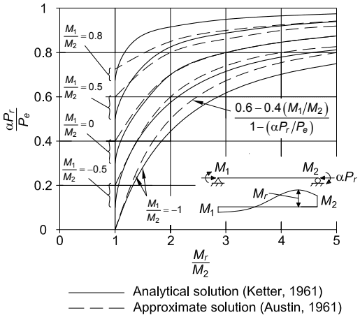
Figure description:
Moment Magnification Factors in Beam-Columns Analytical vs. Approximate solutions
Comparison of Analytical and Approximate Solutions for Moment Magnification
Legend
- Analytical solution (Ketter, 1961 — color: black; symbol: Solid line
- Approximate solution (Austin, 1961 — color: black; symbol: Dashed line
Annotations
- M1/M2 = 0.8 (text_label - position: y = 0.72, x = 1)
- M1/M2 = 0.5 (text_label - position: y = 0.55, x = 1)
- M1/M2 = 0 (text_label - position: y = 0.36, x = 1)
- M1/M2 = -0.5 (text_label - position: y = 0.19, x = 1)
- M1/M2 = -1 (text_label - position: near the curves for ratio -1)
- 0.6 - 0.4(M1/M2 / 1 - (alpha*Pr / Pe (text_label - position: points to approximate solution curves)))
- Beam diagram showing loads alpha*Pr and moments M1, M2 (shaded_area - position: bottom right quadrant)
| Analytical () | Approximate () | Analytical () | Approximate () | Analytical () | Approximate () | Analytical () | Approximate () | Analytical () | Approximate () | |
|---|---|---|---|---|---|---|---|---|---|---|
| 1.0 | 0.68 | 0.72 | 0.48 | 0.60 | 0.32 | 0.40 | 0.18 | 0.20 | 0.00 | 0.00 |
| 1.5 | 0.85 | 0.81 | 0.74 | 0.73 | 0.59 | 0.60 | 0.43 | 0.47 | 0.30 | 0.33 |
| 2.0 | 0.90 | 0.86 | 0.82 | 0.80 | 0.71 | 0.70 | 0.58 | 0.60 | 0.48 | 0.50 |
| 3.0 | 0.95 | 0.91 | 0.89 | 0.87 | 0.82 | 0.80 | 0.74 | 0.73 | 0.64 | 0.67 |
| 4.0 | 0.97 | 0.93 | 0.93 | 0.90 | 0.87 | 0.85 | 0.81 | 0.80 | 0.72 | 0.75 |
| 5.0 | 0.98 | 0.94 | 0.95 | 0.92 | 0.90 | 0.88 | 0.84 | 0.84 | 0.77 | 0.80 |
Notes: The graph shows the relationship between the axial load ratio (alpha*Pr/Pe and the moment magnification factor (Mr/M2 for different end-moment ratios (M1/M2. The dashed lines represent the approximate formula provided in the annotation.)))
Fig. C-A-8.3. Maximum second-order moments, , for beam-columns subjected to applied end moments.
TABLE C-A-8.1 Factor ψ and Equivalent Uniform Moment Factor, Cm
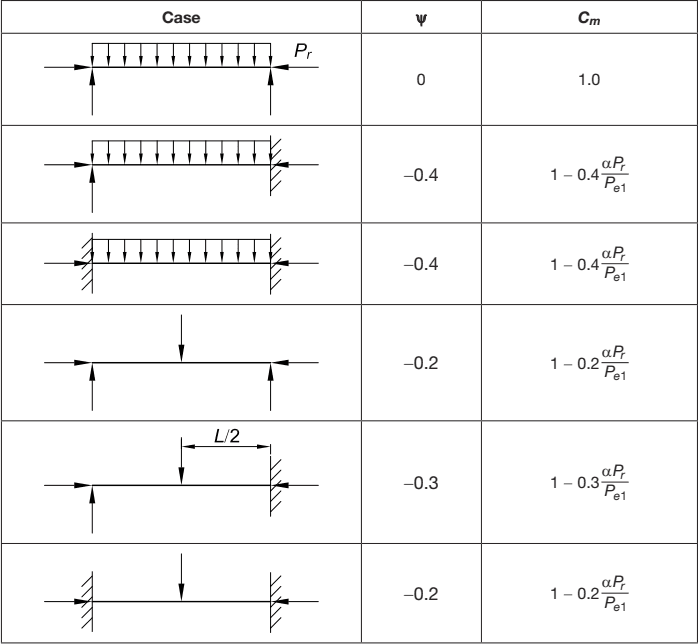
Figure description:
| Case | ||
|---|---|---|
| Simply supported beam with uniform distributed load and axial compression | 0 | 1.0 |
| Pinned-fixed beam with uniform distributed load and axial compression | -0.4 | |
| Fixed-fixed beam with uniform distributed load and axial compression | -0.4 | |
| Simply supported beam with central concentrated point load and axial compression | -0.2 | |
| Pinned-fixed beam with concentrated point load at and axial compression | -0.3 | |
| Fixed-fixed beam with central concentrated point load and axial compression | -0.2 |
Notes: The table provides coefficients for the calculation of the moment gradient factor () for various beam loading and support conditions under axial compression load ().
corresponding to the member end conditions, used in calculating , is less than the laterally unbraced length of the member .
In lieu of using the equations given in Table C-A-8.1, the use of is conservative for all transversely loaded members. It can be shown that the use of for members with restrained ends, as specified in AISC Specifications prior to 2005, can sometimes result in a significant underestimation of the internal moments; therefore, the use of is recommended as a simple conservative approximation for all cases involving transversely loaded members.
In approximating a second-order analysis by amplification of the results of a firstorder analysis, the effective length, , is used in the determination of the elastic critical buckling load, , for a member. This elastic critical buckling load is then used for calculation of the corresponding amplification factor, .
is used to estimate the effects on the nonsway moments, , in compression members. The unbraced length, , is calculated in the plane of bending based on no translation of the ends of the member and is normally set to the laterally unbraced length of the member, unless a smaller value is justified on the basis of analysis.
Because the amplified first-order elastic analysis involves the calculation of elastic buckling loads as a measure of frame and column stiffness, only elastic effective length K-factors are appropriate for this use.
Summary—Application of Multipliers and . There is a single value for each story and each direction of lateral translation of the story, say and for the two global directions. Multiplier is applicable to all axial and shear forces and moments produced by story translation in the global X-direction. Thus, in the common case where gravity load produces no lateral translation and all translation is the result of lateral load in the -direction, is applicable to all axial and shear forces, and moments produced by lateral load in the global -direction. Similarly, is applicable in the -direction.
Note that and are associated with global axes and and the direction of story translation or loading, but are completely unrelated to the direction of bending of individual members. Thus, for example, if lateral load or translation in the global X-direction causes moments and about member x- and y-axes in a particular member, must be applied to both and .
There is a separate value for every member subjected to compression and flexure and each direction of bending of the member, say and for the two member axes. Multiplier is applicable to the member -axis moment, regardless of the load that causes that moment. Similarly, is applicable to the member -axis moment, regardless of the load that causes that moment.