C-G2G2 I-shaped members and channels
PDF page 464 · AISC 360-22
Two shear strength prediction methods are presented. The method in Section G2.1 accounts for the web shear post-buckling strength through Rotated Stress Field Theory in members with unstiffened webs and members with transverse stiffeners spaced at or smaller. The method of Sections G2.2 and G2.3 accounts for the web shear post-buckling strength through tension field action in interior and end panels, respectively, of members with stiffeners spaced at or smaller. Transverse stiffeners, or components providing equivalent restraint of out-of-plane deformation of the web, may be necessary at the member ends and at supports.
G2.1 Shear Strength of Webs
Section G2.1 addresses the shear strength of I-shaped members subjected to shear and bending in the plane of the web. The provisions in this section apply when postbuckling strength develops due to web stress redistribution.
The nominal shear strength of a web is defined by Equation G2-1, a product of the shear yield force, , and the shear post-buckling strength reduction factor, . The formulation is based on the Rotated Stress Field Theory (Höglund, 1997), which includes post-buckling strength due to web stress redistribution in members with or without transverse stiffeners. Höglund presented equations for members with rigid end posts (in essence, vertical beams spanning between flanges) and nonrigid end posts, such as regular bearing stiffeners. The latter equation was written in the form of the familiar formulation from prior AISC Specifications and modified slightly for use in Section G2.1 (Daley et al., 2016; Studer et al., 2015).
The provisions in Section G2.1(a) for rolled I-shaped members with are similar to the 1999 and earlier LRFD Specifications, with the exception that has been increased from 0.90 to 1.00 (with a corresponding decrease of the safety factor from 1.67 to 1.50), thus making these provisions consistent with the 1989 provisions for allowable stress design (AISC, 1989). The value of of 1.00 is justified by comparison with experimental test data and recognizes the minor consequences of shear yielding, as compared to tension and compression yielding, on the overall
performance of rolled I-shaped members. This increase is applicable only to the shear yielding limit state of rolled I-shaped members.
Section G2.1(b) uses the shear post-buckling strength reduction factor, , shown in Figure C-G2.1. The curve for has two segments, whereas prior to 2016, Section G2.1 provisions for had three segments (AISC, 2010).
For webs with , the nominal shear strength, , is based on shear yielding of the web, with as given by Equation G2-3. This yield- ing limit was determined by slightly increasing the limit from Höglund (1997) to match the previous yielding limit, which was based on Cooper et al. (1978).
When , the web shear strength is based on the shear buckling and subsequent post-buckling strength of a web with nonrigid end posts. The resulting strength reduction factor, , given by Equation G2-4, was determined by dividing the Höglund (1997) buckling plus post-buckling strength by the shear yield strength and increasing that ratio slightly to better match experimental measurements (Daley et al., 2016; Studer et al., 2015).
The plate buckling coefficient, , for panels subjected to pure shear having simple supports on all four sides is given by the following (Ziemian, 2010):
(C-G2-1)
For simplicity, these equations have been simplified without loss of accuracy and were first introduced in AASHTO (2014) as the following equation, which is based on Vincent (1969):
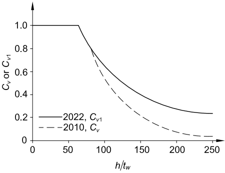
Figure description:
Comparison of Cv and Cv1 Shear Coefficients
Cv or Cv1 versus h/t_w
Legend
- 2022, Cv1 — color: black; symbol: Solid line
- 2010, Cv — color: black; symbol: Dashed line
| h/t_w | 2022, Cv1 | 2010, Cv |\n| :--- | :--- | :--- |\n| 0 | 1.00 | 1.00 |\n| 25 | 1.00 | 1.00 |\n| 50 | 1.00 | 1.00 |\n| 65 | 1.00 | 1.00 |\n| 75 | 0.88 | 0.88 |\n| 83 | 0.80 | 0.80 |\n| 100 | 0.66 | 0.55 |\n| 125 | 0.51 | 0.35 |\n| 150 | 0.41 | 0.22 |\n| 175 | 0.34 | 0.14 |\n| 200 | 0.29 | 0.08 |\n| 225 | 0.26 | 0.05 |\n| 250 | 0.24 | 0.04 |
Notes: The chart compares the shear coefficient standards from 2022 (Cv1 and 2010 (Cv. Both curves start at 1.0 and follow the same decay path from approximately h/t_w = 65 until they diverge around h/t_w = 83. Beyond this point, the 2022 standard (Cv1 maintains a higher coefficient than the 2010 standard (Cv.))))
Fig. C-G2.1. Shear buckling coefficient for .
(C-G2-2)
The plate buckling coefficient, , is 5.34 for web panels with an aspect ratio, , exceeding 3.0 . This value is slightly larger than the value of 5.0 used in AISC Specifications prior to 2016, and is consistent with Höglund's developments (Höglund, 1997).
2
AISC Specifications before 2016 limited to , which was based on the following statement by Basler (1961): "In the range of high web slenderness ratios, the stiffener spacing should not be arbitrarily large. Although the web might still be sufficient to carry the shear, the distortions could be almost beyond control in fabrication and under load." The experimental evidence shows that I-shaped members develop the calculated resistances without the need for this restriction (White and Barker, 2008; White et al., 2008). Furthermore, for , Equation F13-4 limits the maximum to 232 for , and for , Equation F13-3 limits the web slenderness to 289 for . These limits are considered sufficient to limit distortions during fabrication and handling. The engineer should be aware of the fact that sections with highly slender webs are more apt to be controlled by the web local yielding, web local crippling, and/or web compression buckling limit states of Sections J10.2, J10.3, and J10.5. Therefore, these limit states may limit the maximum practical web slenderness in some situations.
G2.2 Shear Strength of Interior Web Panels with Considering Tension Field Action
The panels of the web of a built-up member, bounded on the top and bottom by the flanges and on each side by transverse stiffeners, are capable of carrying loads far in excess of their web elastic buckling strength. Upon reaching the theoretical web elastic buckling strength, slight lateral displacements of the web will have developed. These deformations are of no structural significance, because other means are still present to provide further shear resistance.
When transverse stiffeners are properly spaced and are stiff enough to resist out-of-plane movement of the post-buckled web, significant diagonal tension fields form in the web panels prior to the shear yielding resistance. The web in effect acts like a Pratt truss composed of tension diagonals and compression verticals that are stabilized by the transverse stiffeners. This effective Pratt truss furnishes the strength to resist applied shear forces unaccounted for by the elastic buckling theory, but the enhanced resistance due to tension field forces is reduced when the panel aspect ratio becomes large. For this reason, the inclusion of tension field action is not permitted when exceeds 3.0.
Analytical methods based on tension field action have been developed (Basler and Thürlimann, 1963; Basler, 1961) and corroborated in an extensive program of tests (Basler et al., 1960). Equation G2-7 is based on this research. The second term in the bracket represents the relative increase of the panel shear strength due to tension field action. The merits of Equation G2-7 relative to various alternative representations of web shear resistance are evaluated and Equation G2-7 is recommended for
characterization of the shear strength of stiffened interior web panels in White and Barker (2008).
AISC Specifications prior to 2005 required explicit consideration of the interaction between the flexural and shear strengths when the web is designed using tension field action. White et al. (2008) show that the interaction between the shear and flexural resistances may be neglected by using a smaller tension field action shear strength for beams with or or . Section G2.2 disallows the use of the traditional complete tension field action, Equation G2-7, for I-shaped members with relatively small flange-to-web proportions identified by these limits. For cases where these limits are violated, Equation G2-8 gives an applicable reduced tension field action resistance referred to as the “true Basler” tension field resistance. The true Basler resistance is based on the development of only a partial tension field, whereas Equation G2-7 is based on the development of a theoretical complete ten sion field. Similar limits are specified in AASHTO (2014).
Consideration of shear and bending interaction, which was required prior to 2010 (AISC, 2010), is not required because the shear and flexural resistances can be calculated with a sufficient margin of safety without considering this effect (White et al., 2008; Daley et al., 2016).
G2.3 Shear Strength of End Web Panels with Considering Tension Field Action
The key requirement in the development of tension field action for the interior panels of built-up I-shaped members is the ability of the stiffeners to provide sufficient flexural rigidity to stabilize the web along their length. In the case of end panels, there is a panel only on one side. The anchorage of the tension field was, thus, thought to be limited and its contribution had been neglected since the shear strength equation with tension-field action was introduced in the Specification in 1961 (AISC, 1961). Recent testing of large-size steel girders shows, however, that this design approach for end panels is very conservative (Kim and Uang, 2021). Based on results from both testing and finite element simulation, it is shown that tension field action actually can develop by forming plastic hinges in the flanges and bearing stiffeners shown in Figure C-G2.2. Equation G2-12 has the same format as Equation G2-7, except that a parameter is included in the second term in the bracket in Equation G2-12 to reflect the contribution from partial tension field action. The term given by Equation G2-13 requires that the plastic moments of the flanges and bearing stiffeners at the support be computed. A small portion of the web with a width is included in the sections to compute these plastic moments (see Figure C-G2.3). When the web extends beyond the support, the overhang portion of the web should not be taken larger than ; it is assumed that the portion beyond this length is ineffective due to flexural buckling when a plastic hinge is formed at location J in Figure C-G2.2. For interior panels, two equations (Equations G2-7 and G2-8) are provided, depending on the flange areas relative to the web area. Such distinction is not needed for end panels because the effect of flange area is directly reflected in the value of . Equation G2-12 is developed for doubly symmetric members with equal flange areas. When the top and bottom flanges are not the same, is based on the smaller value from the top or bottom flange.
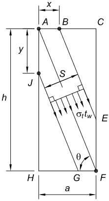
Figure description:
Key Entities and Information:
- Subject: Schematic of an assumed plastic mechanism in a structural panel.
- Dimensions:
- h: Total panel height.
- a: Total panel width.
- x: Horizontal distance from corner to point .
- y: Vertical distance from corner to point .
- s: Perpendicular width of the diagonal tension strip.
- Geometric Features:
- : Angle of the diagonal tension field relative to the horizontal.
- Nodes: Key points labeled through ; points and are highlighted as hinges/pivots.
- Applied Forces:
- : Represents the tension field stress acting within the diagonal band.
Fig. C-G2.2. Assumed plastic mechanism.
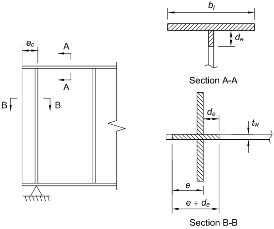
Figure description:
The image displays engineering diagrams labeled as Fig. C-G2.3, showing effective cross-sections for computing and in a structural plastic mechanism.
Key Entities and Details:
- Main Diagram: Shows a girder section with vertical stiffeners and a pin support. A distance is noted from the end to the first stiffener.
- Section A-A: Represents the effective cross-section for .
- : Flange width.
- : Effective depth of the shaded web portion beneath the flange.
- Section B-B: Represents the effective cross-section for .
- : Web thickness.
- : Distance from the web edge to the stiffener center.
- : Effective length of the web extending past the stiffener.
- : Total effective length of the shaded web and stiffener area.
Fig. C-G2.3. Effective cross sections for computing and .
G2.4 Transverse Stiffeners
Numerous studies (Horne and Grayson, 1983; Rahal and Harding, 1990a, 1990b, 1991; Stanway et al., 1993, 1996; Lee et al., 2002b; Xie and Chapman, 2003; Kim et al., 2007; Kim and White, 2014) have shown that transverse stiffeners in I-girders designed for shear post-buckling strength, including tension field action, are loaded predominantly in bending due to the restraint they provide to lateral deflection of the web. Generally, there is evidence of some axial compression in the transverse stiffeners due to the tension field, but even in the most slender web plates permitted by this Specification, the effect of the axial compression transmitted from the post-buckled web plate is typically minor compared to the lateral loading effect. Therefore, the transverse stiffener area requirement from prior AISC Specifications is no longer specified. Rather, the demands on the stiffener flexural rigidity are increased in situations where the post-buckling resistance of the web is relied upon. Equation G2-17 is the same requirement as specified in AASHTO (2014).