Table K4.2
PDF page 237 · AISC 360-22
Available Strengths of Rectangular HSS-to-HSS Moment Connections
| Connection Type | Connection Available Flexural Strength |
|---|---|
| Branch(es) under out-of-plane bending T- and cross-connections tb Hb M H B | Limit state: chord sidewall local yielding Mn-op = F′yt (B - t) (Hb + 5t) (K4-6) φ = 1.00 (LRFD) Ω = 1.50 (ASD) |
| Limit state: chord distortional failure, for T-connections and unbalanced cross-connections Mn-op = 2F′yt [ Hbt + √BHt(B+H) ] (K4-7) φ = 0.95 (LRFD) Ω = 1.58 (ASD) | |
| Branch(es) under in-plane bending T- and cross-connections Hb tb Bb M θ t H B Not present for T-connection | Limit state: sidewall local yielding When β ≥ 0.85 Mn-ip = 0.5F′yt (Hb + 5t)2 (K4-8) φ = 1.00 (LRFD) Ω = 1.50 (ASD) |
| For T- and cross-connections, with branch(es) under combined axial load, in-plane bending, and out-of-plane bending, or any combination of these load effects Pr/Pc + Mr-ip/Mc-ip + Mr-op/Mc-op ≤ 1.0 (K4-9) Pr = required axial strength in branch using LRFD or ASD load combinations, kips (N) Mr-ip = required in-plane flexural strength in branch using LRFD or ASD load combinations, kip-in. (N-mm) Mr-op = required out-of-plane flexural strength in branch using LRFD or ASD load combina-tions, kip-in. (N-mm) Pc = available axial strength, kips (N) Mc-ip = available strength for in-plane bending, kip-in. (N-mm) Mc-op = available strength for out-of-plane bending, kip-in. (N-mm) = φMn-op (LRFD); = Mn-op/Ω (ASD) | |
| Functions | |
| F′y = Fy for T-connections and 0.8Fy for cross-connections Pro = Pu for LRFD, and Pa for ASD; Mro = Mu for LRFD, and Ma for ASD | |
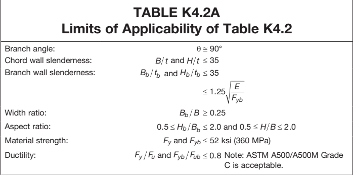
Figure description:
TABLE K4.2A: Limits of Applicability of Table K4.2
| Parameter | Limit |
|---|---|
| Branch angle | |
| Chord wall slenderness | and |
| Branch wall slenderness | and and |
| Width ratio | |
| Aspect ratio | and |
| Material strength | and ksi (360 MPa) |
| Ductility | and (Note: ASTM A500/A500M Grade C is acceptable) |
where
nominal stress of weld metal in accordance with Chapter J, ksi (MPa)
- effective elastic section modulus of welds for in-plane bending (Table K5.1), in.
- effective elastic section modulus of welds for out-of-plane bending (Table K5.1), in.
User Note: Where flexure results in tension in any load case in the weld the directional strength increase factor cannot exceed 1.0 in fillet welds to the end of rectangular HSS.
When a rectangular overlapped K-connection has been designed in accordance with Table K3.2, and the branch member component forces normal to the chord are 80% balanced (in other words, the branch member forces normal to the chord face differ by no more than 20%), the hidden weld under an overlapping branch may be omitted if the remaining welds to the overlapped branch everywhere develop the full capacity of the overlapped branch member walls.
The weld checks in Tables K5.1 and K5.2 are not required if the welds are capable of developing the full strength of the branch member wall along its entire perimeter (or a plate along its entire length).
User Note: The approach used here to allow downsizing of welds assumes a constant weld size around the full perimeter of the HSS branch. Special attention is required for equal width (or near-equal width) connections to rectangular HSS, which combine partial-joint-penetration groove welds along the matched edges of the connection, with fillet welds generally across the chord member face.
| TABLE K5.1 Effective Weld Properties for Connections to Rectangular HSS | |
|---|---|
| Connection Type | Weld Properties |
| Transverse plate T- and cross-connections under plate axial load [Diagram with labels: R, tp, H, t, Bb, B] | Effective weld properties le = 2Be (K5-4) where le = total effective weld length for welds on both sides of the transverse plate, in. (mm) |
| T-, Y-, and cross-connections under branch axial load or bending [Diagram with labels: M or P, tb, Hb, Bb, A, θ, H, t, B, Note: Not present for T- or Y-connection] [Section A-A Diagram with labels: Hb/sinθ, Be/2] Section A-A: Effective weld | Effective weld properties le = 2Hb / sinθ + 2Be (K5-5) Sip = (tw / 3)(Hb / sinθ)2 + twBe(Hb / sinθ) (K5-6) Sop = tw(Hb / sinθ)Bb + (tw / 3)(Be)2 - ((tw / 3)(Bb-Be)3) / Bb (K5-7) When β > 0.85 or θ > 50°, Be/2 shall not exceed Bb/4. |
| Gapped K-connections under branch axial load [Diagram with labels: Hb, tb, A, θ, P, g, +e, H, t, B] [Section A-A Diagram with labels: Hb - 1.2tb / sinθ, Bb - 1.2tb] 4th side effective when θ ≤ 50° Section A-A: Effective weld for ≥ 60° | Effective weld properties When θ ≤ 50° le = 2(Hb - 1.2tb) / sinθ + 2(Bb - 1.2tb) (K5-8) When θ ≥ 60° le = 2(Hb - 1.2tb) / sinθ + Bb - 1.2tb (K5-9) When 50° < θ < 60°, linear interpolation shall be used to determine le. |