Table K5.1: (continued)
PDF page 240 · AISC 360-22
Effective Weld Properties for Connections to Rectangular HSS
Connection Type Weld Properties
Overlapped K-connections under branch axial load
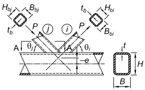
Figure description:
Key Information: Overlapped K-Connection Diagram
Structural Components and Parameters:
- Main Member (Chord:
- : Height, width, and wall thickness of the rectangular chord.
- : Eccentricity (vertical distance between branch axis intersection and chord centerline.
- Overlapping Branch (:
- : Height, width, and wall thickness.
- : Angle of inclination to the chord.
- : Applied axial tensile load.
- Overlapped Branch (:
- : Height, width, and wall thickness.
- : Angle of inclination to the chord.
- : Applied axial compressive load.
Connection Details:
- Type: Overlapped K-connection where member sits partially on member .
- Load State: Branches are subjected to opposing axial loads (.
Overlapping member effective weld properties (all dimensions are for the overlapping branch, i)
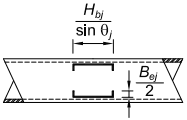
Figure description:
- Technical diagram showing effective weld properties for an overlapping branch member.
- Section A-A: Effective weld layout for conditions where and .
- Horizontal Dimension:
- Vertical Dimension:
- Key Entities: Represents the weld configuration on a structural member with dashed and solid lines indicating weld boundaries.
Section A-A: Effectve weld when and
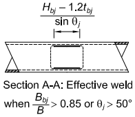
Figure description:
Key Information: Section A-A: Effective Weld
- Subject: Structural diagram for calculating effective weld length in a connection.
- Formula:
- Application Condition: This specific calculation for Section A-A applies when:
- OR
- Visual Elements: Diagram shows a cross-section of a rectangular or square hollow section with the dimension for the effective weld indicated between two internal points.
Note that the force arrows shown for overlapped K-connections may be reversed; and control member identification.
When
(K5-10)
When 50% ≤ Ov < 80%
(K5-11)
When
(K5-12)
(K3-13)
When or shall not exceed and when or shall not exceed .
Subscript refers to the overlapping branch. Subscript refers to the overlapped branch.
Overlapped member effective weld properties (all dimensions are for the overlapped branch, j)
(K5-13)
(K5-14)
When or
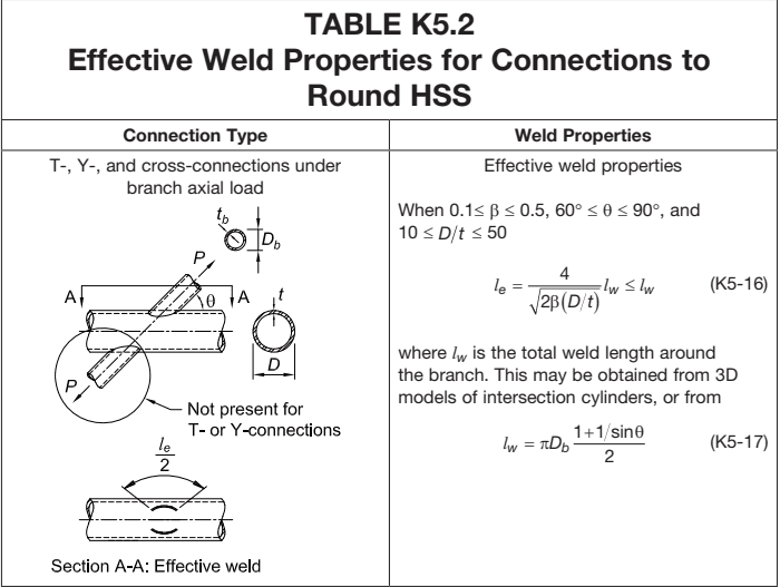
Figure description:
Effective Weld Properties for Connections to Round HSS
TABLE K5.2 Effective Weld Properties for Connections to Round HSS
Annotations
- Not present for T- or Y-connections (text_label - position: Referring to the bottom branch of the cross-connection diagram)
- Section A-A: Effective weld (text_label - position: Label for the bottom-left diagram showing the arc of effective weld)
- l_e/2 (text_label - position: Arc angle label in Section A-A diagram)
- D_b, t_b (text_label - position: Dimensions of the branch cross-section)
- D, t (text_label - position: Dimensions of the chord cross-section)
| Connection Type | Weld Properties |
|---|---|
| T-, Y-, and cross-connections under branch axial load | Effective weld properties When 0.1 ≤ ̢ ≤ 0.5, 60° ≤ θ ≤ 90°, and 10 ≤ D/t ≤ 50 (K5-16 where is the total weld length around the branch. This may be obtained from 3D models of intersection cylinders, or from (K5-17))) |
Notes: The table provides design formulas for determining the effective weld length (l_e and total weld length (l_w for various HSS connections based on geometric parameters and loading conditions.))