C-H2H2 Unsymmetric and other members subjected to flexure and axial force
PDF page 478 · AISC 360-22
The provisions of Section H1 apply to beam-columns with cross sections that are either doubly or singly symmetric. However, there are many cross sections that are unsymmetrical, such as unequal-leg angles and any number of possible fabricated sections. For these situations, the interaction equations of Section H1 may not be appropriate. The linear interaction,
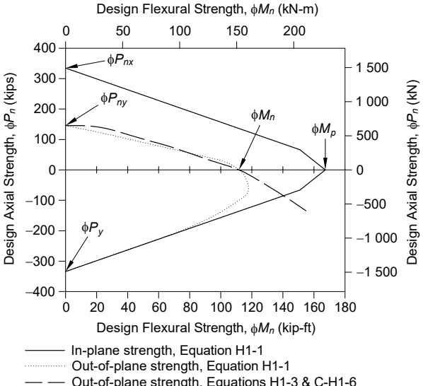
Figure description:
Design Strengths for Combined Axial and Flexural Loads
Legend
- In-plane strength, Equation H1-1 — color: black; symbol: Solid line
- Out-of-plane strength, Equation H1-1 — color: black; symbol: Dotted line
- Out-of-plane strength, Equations H1-3 & C-H1-6 — color: black; symbol: Dashed line
Annotations
- (text_label - position: y = 335, x = 0)
- (text_label - position: y = 145, x = 0)
- (text_label - position: y = -335, x = 0)
- (text_label - position: x = 113, y = 0)
- (text_label - position: x = 167, y = 0)
| Design Flexural Strength, (kip-ft) | Design Flexural Strength, (kN-m) | Design Axial Strength, (kips - In-plane (Eq H1-1)) | Design Axial Strength, (kips - Out-of-plane (Eq H1-1)) | Design Axial Strength, (kips - Out-of-plane (Eqs H1-3 & C-H1-6)) | Design Axial Strength, (kN - In-plane (Eq H1-1)) | Design Axial Strength, (kN - Out-of-plane (Eq H1-1)) | Design Axial Strength, (kN - Out-of-plane (Eqs H1-3 & C-H1-6)) |
|---|---|---|---|---|---|---|---|
| 0 | 0 | 335 | 145 | 150 | 1490 | 645 | 667 |
| 20 | 27 | 299 | 142 | 114 | 1330 | 632 | 507 |
| 40 | 54 | 263 | 132 | 77 | 1170 | 587 | 342 |
| 60 | 81 | 227 | 115 | 41 | 1010 | 512 | 182 |
| 80 | 108 | 191 | 86 | 5 | 850 | 383 | 22 |
| 100 | 136 | 155 | 45 | -32 | 689 | 200 | -142 |
| 113 | 153 | 131 | 0 | -55 | 583 | 0 | -245 |
| 120 | 163 | 119 | -55 | -68 | 529 | -245 | -302 |
| 140 | 190 | 83 | -104 | 369 | -463 | ||
| 150 | 203 | 65 | -123 | 289 | -547 | ||
| 167 | 226 | 0 | 0 | ||||
| 150 | 203 | -65 | -289 | ||||
| 140 | 190 | -85 | -378 | ||||
| 120 | 163 | -125 | -556 | ||||
| 100 | 165 | -160 | -712 | ||||
| 80 | 108 | -195 | -867 | ||||
| 60 | 81 | -230 | -1023 | ||||
| 40 | 54 | -265 | -1179 | ||||
| 20 | 27 | -300 | -1334 | ||||
| 0 | 0 | -335 | -1490 |
Notes: The chart displays interaction curves for the design of steel members under combined axial and flexural loads. It uses dual units for both axes: kip-ft and kN-m for flexural strength, and kips and kN for axial strength. The strength envelopes are based on different AISC Specification equations.
Out-of-plane strength, Equations H1-3 & C-H1-6
Fig. C-H1.5. Beam-columns under compressive and tensile axial force (tension is shown as negative) (LRFD) .
provides a conservative and simple way to deal with such problems. The lower case stresses, , are the required axial and flexural stresses computed by elastic analysis for the applicable loads, including second-order effects where appropriate, and the upper case stresses, , are the available stresses corresponding to the limit state of yielding or buckling. The subscripts and refer to the required and available stresses, respectively, while the subscripts and refer to the principal axes of the unsymmetric cross section. This Specification leaves the option to the designer to use the Section H2 interaction equation for cross sections that would qualify for the more liberal interaction equations of Section H1.
The interaction equation, Equation H2-1, applies equally to the case where the axial force is in tension. Equation H2-1 was written in stress format as an aid in examining the condition at the various critical locations of the unsymmetric member. For unsymmetrical sections with uniaxial or biaxial flexure, the critical condition is dependent on the resultant direction of the moment. This is also true for singly symmetric members, such as for -axis flexure of tees. The same elastic section properties are used to compute the corresponding required and available flexural stress terms, which means that the moment ratio will be the same as the stress ratio.
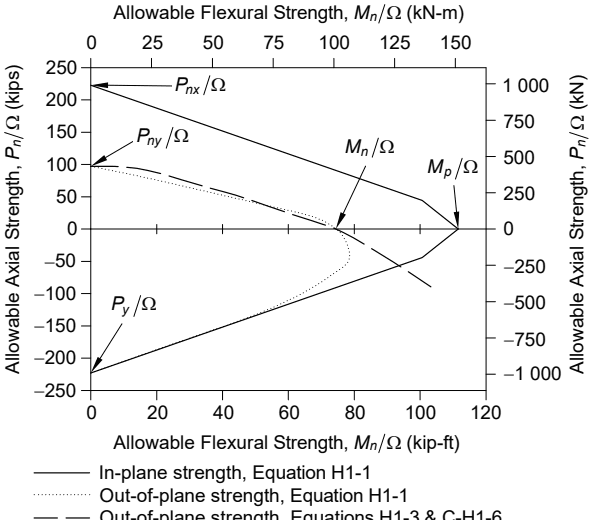
Figure description:
Allowable Axial Strength vs. Allowable Flexural Strength Interaction
Legend
- In-plane strength, Equation H1-1 — color: black; symbol: Solid line
- Out-of-plane strength, Equation H1-1 — color: black; symbol: Dotted line
- Out-of-plane strength, Equations H1-3 & C-H1-6 — color: black; symbol: Dashed line
Annotations
- (text_label - position: x = 0, y = 225)
- (text_label - position: x = 0, y = 98)
- (text_label - position: x = 0, y = -225)
- (text_label - position: x = 75, y = 0)
- (text_label - position: x = 111, y = 0)
| Series | Allowable Flexural Strength, (kip-ft) | Allowable Axial Strength, (kips) |
|---|---|---|
| In-plane strength, Equation H1-1 | 0 | 225 |
| In-plane strength, Equation H1-1 | 20 | 190 |
| In-plane strength, Equation H1-1 | 40 | 150 |
| In-plane strength, Equation H1-1 | 60 | 115 |
| In-plane strength, Equation H1-1 | 80 | 80 |
| In-plane strength, Equation H1-1 | 100 | 45 |
| In-plane strength, Equation H1-1 | 111 | 0 |
| In-plane strength, Equation H1-1 | 100 | -45 |
| In-plane strength, Equation H1-1 | 80 | -70 |
| In-plane strength, Equation H1-1 | 60 | -110 |
| In-plane strength, Equation H1-1 | 40 | -150 |
| In-plane strength, Equation H1-1 | 20 | -190 |
| In-plane strength, Equation H1-1 | 0 | -225 |
| Out-of-plane strength, Equation H1-1 | 0 | 95 |
| Out-of-plane strength, Equation H1-1 | 20 | 75 |
| Out-of-plane strength, Equation H1-1 | 40 | 55 |
| Out-of-plane strength, Equation H1-1 | 60 | 30 |
| Out-of-plane strength, Equation H1-1 | 75 | 0 |
| Out-of-plane strength, Equation H1-1 | 80 | -40 |
| Out-of-plane strength, Equation H1-1 | 75 | -65 |
| Out-of-plane strength, Equation H1-1 | 60 | -85 |
| Out-of-plane strength, Equation H1-1 | 40 | -105 |
| Out-of-plane strength, Equation H1-1 | 20 | -125 |
| Out-of-plane strength, Equation H1-1 | 0 | -145 |
| Out-of-plane strength, Equations H1-3 & C-H1-6 | 0 | 98 |
| Out-of-plane strength, Equations H1-3 & C-H1-6 | 20 | 60 |
| Out-of-plane strength, Equations H1-3 & C-H1-6 | 40 | 25 |
| Out-of-plane strength, Equations H1-3 & C-H1-6 | 55 | 0 |
| Out-of-plane strength, Equations H1-3 & C-H1-6 | 80 | -55 |
| Out-of-plane strength, Equations H1-3 & C-H1-6 | 105 | -90 |
Notes: The chart utilizes dual axes. The flexural strength is measured in kip-ft (bottom and kN-m (top, while axial strength is measured in kips (left and kN (right. Data points listed in the table are estimated using the primary axes (kip-ft and kips.)))))
Out-of-plane strength, Equations H1-3 & C-H1-6
Fig. C-H1.6. Beam-columns under compressive and tensile axial force (tension is shown as negative) (ASD)
.
There are two approaches for using Equation H2-1:
- (a) Strictly using Equation H2-1 for the interaction of the critical moment about each principal axis, there is only one flexural stress ratio term for every critical location because moment and stress ratios are the same as noted previously. In this case, one would algebraically add the value of each of the ratio terms to obtain the critical condition at one of the extreme fibers.
Using Equation H2-1 is the conservative approach and is recommended for examining members such as single angles. The available flexural stresses at a particular location (tip of short or long leg or at the heel) are based on the yielding limit moment, the local buckling limit moment, or the lateral-torsional buckling moment, consistent with the sign of the required flexural stress. In each case, the yield moment should be based on the smallest section modulus about the axis being considered. One would check the stress condition at the tip of the long and short legs and at the heel and find that at one of the locations the stress ratios would be critical.
- (b) For certain load components, where the critical stress can transition from tension at one point on the cross section to compression at another, it may be advantageous to consider two interaction relationships depending on the magnitude of each component. This is permitted by the sentence at the end of Section H2 that permits a more detailed analysis in lieu of Equation H2-1 for the interaction of flexure and tension.
As an example, for a tee with flexure about both the - and -axes creating tension at the tip of the stem, compression at the flange could control or tension at the stem could control the design. If y-axis flexure is large relative to -axis flexure, the stress ratio need only be checked for compression at the flange using corresponding design compressive stress limits. However, if the y-axis flexure is small relative to the -axis flexure, then one would check the tensile stress condition at the tip of the stem, this limit being independent of the amount of the -axis flexure. The two differing interaction expressions are
at tee flange
and
at tee stem
The interaction diagrams for biaxial flexure of a WT using both approaches are illustrated in Figure C-H2.1.
Another situation in which one could benefit from consideration of more than one interaction relationship occurs when axial tension is combined with a flexural compression limit based on local buckling or lateral-torsional buckling. An example of this is when the stem of a tee in flexural compression is combined with axial tension. The introduction of the axial tension will reduce the compression that imposed the
buckling stress limit. With a required large axial tension and a relatively small flexural compression, the design flexural stress could be set at the yield limit at the stem. The interaction equation is then,
(C-H2-1)
where is the flange tension stress based on reaching in the stem. There could be justification for using equal to in this expression.
This interaction relationship would hold until the interaction between the flexural compressive stress at the stem with based on the local or lateral-torsional buckling limit, as increased by the axial tension, would control, resulting in the following interaction:
(C-H2-2)
The interaction diagrams for this case, using both approaches, are illustrated in Figure C-H2.2.