C-H3H3 Members subjected to torsion and combined torsion, flexure, shear, and/or axial force
PDF page 481 · AISC 360-22
Section H3 provides provisions for cases not covered in the previous two sections. The first two parts of this section address the design of HSS members, and the third part is a general provision directed to cases where the designer encounters torsion in addition to normal stresses and shear stresses.
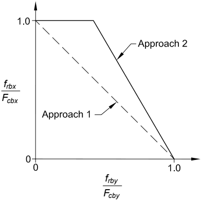
Figure description:
Comparison of Two Interaction Approaches
Legend
- Approach 1 — color: black; symbol: Dashed line
- Approach 2 — color: black; symbol: Solid line
Annotations
- Approach 1 (text_label - position: points to the dashed line)
- Approach 2 (text_label - position: points to the solid line)
| f_rby / F_cby | Approach 1 (f_rbx / F_cbx) | Approach 2 (f_rbx / F_cbx) |
|---|---|---|
| 0.0 | 1.0 | 1.0 |
| 0.4 | 0.6 | 1.0 |
| 1.0 | 0.0 | 0.0 |
Notes: The chart represents interaction curves for normalized structural force ratios. Approach 1 is a linear interaction represented by the equation (f_rby / F_cby + (f_rbx / F_cbx = 1.0. Approach 2 is a bilinear interaction that maintains a constant ratio of 1.0 for f_rbx / F_cbx until f_rby / F_cby reaches approximately 0.4, after which it decreases linearly to 0.0 at f_rby / F_cby = 1.0.))
Fig. C-H2.1. WT with biaxial flexure.
H3.1 Round and Rectangular HSS Subjected to Torsion
Hollow structural sections (HSS) are frequently used in space-frame construction and in other situations wherein significant torsional moments must be resisted by the members. Because of its closed cross section, an HSS is far more efficient in resisting torsion than an open cross section, such as an I-shape or a channel. While normal and shear stresses due to restrained warping are usually significant in shapes of open cross section, they are insignificant in closed cross sections. The total torsional moment can be assumed to be resisted by pure torsional shear stresses. These are often referred to in the literature as St. Venant torsional stresses.
The pure torsional shear stress in HSS is assumed to be uniformly distributed along the wall of the cross section, and it is equal to the torsional moment divided by a torsional shear constant for the cross section, . In a limit state format, the nominal torsional resisting moment is the torsional shear constant times the critical shear stress, .
For round HSS, the torsional shear constant is equal to the polar moment of inertia divided by the radius:
(C-H3-1)
where is the inside diameter.
For rectangular HSS, the torsional shear constant is obtained as using the membrane analogy (Timoshenko, 1956), where is the area bounded by the midline of the section. Conservatively assuming an outside corner radius of , the midline radius is and
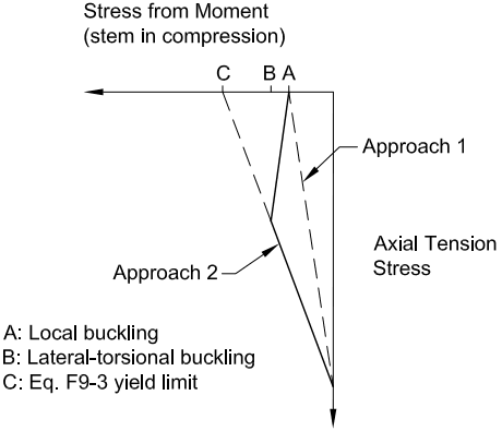
Figure description:
Structural Stress Interaction Diagram
Interaction of Stress from Moment and Axial Tension Stress
Legend
- Approach 1 — color: black; symbol: Dashed line
- Approach 2 — color: black; symbol: Solid line
Annotations
- A: Local buckling (text_label - position: x-axis point A)
- B: Lateral-torsional buckling (text_label - position: x-axis point B)
- C: Eq. F9-3 yield limit (text_label - position: x-axis point C)
| Series | Stress from Moment (stem in compression) | Axial Tension Stress |
|---|---|---|
| Approach 1 | 0.0 | Max |
| Approach 1 | A | 0.0 |
| Approach 2 | 0.0 | Max |
| Approach 2 | B' (kink point) | Intermediate |
| Approach 2 | A | 0.0 |
| Reference (Yield Limit) | 0.0 | Max |
| Reference (Yield Limit) | C | 0.0 |
| Reference (Local Buckling) | 0.0 | 0.0 |
| Reference (Local Buckling) | A | 0.0 |
Notes: The chart illustrates two approaches for determining stress limits in a structural component. Approach 1 is a simple linear interaction between maximum axial tension and local buckling (point A. Approach 2 is a piecewise linear interaction that follows the yield limit (point C but is modified by lateral-torsional buckling (point B and local buckling (point A. The 'Stress from Moment' axis increases to the left from a vertical origin representing zero moment stress. The 'Axial Tension Stress' axis increases downwards from a horizontal origin representing zero axial tension.))))
Fig. C-H2.2. WT with flexural compression on the stem plus axial tension.
A。=(B−1)(H − 1)− 91² (4—ñ) (C-H3-2) 4
resulting in
(C-H3-3)
The resistance factor, , and the safety factor, , are the same as for flexural shear in Chapter G.
When considering local buckling in round HSS subjected to torsion, most structural members will either be long or of moderate length and the provisions for short cylinders will not apply. The elastic local buckling strength of long cylinders is unaffected by end conditions and the critical stress is given in Ziemian (2010) as
The theoretical value of is 0.73 but a value of 0.6 is recommended to account for initial imperfections. An equation for the elastic local buckling stress for round HSS of moderate length where the edges are not fixed at the ends against rotation is given in Schilling (1965) and Ziemian (2010) as
(C-H3-5)
This equation includes a 15% reduction to account for initial imperfections. The length effect is included in this equation for simple end conditions, and the approximately 10% increase in buckling strength is neglected for edges fixed at the end. A limitation is provided so that the shear yield strength, , is not exceeded.
The critical stress provisions for rectangular HSS are identical to the flexural shear provisions of Section G4 with the shear buckling coefficient equal to . The shear distribution due to torsion is uniform in the longest sides of a rectangular HSS, and this is the same distribution that is assumed to exist in the web of an I-shaped beam. Therefore, it is reasonable that the provisions for buckling are the same in both cases.
H3.2 HSS Subjected to Combined Torsion, Shear, Flexure, and Axial Force
Several interaction equation forms have been proposed in the literature for load combinations that produce both normal and shear stresses. In one common form, the normal and shear stresses are combined elliptically with the sum of the squares (Felton and Dobbs, 1967):
(C-H3-6)
In a second form, the first power of the ratio of the normal stresses is used:
(C-H3-7)
The latter form is somewhat more conservative, but not overly so (Schilling, 1965), and this is the form used in this Specification:
(C-H3-8)
where the terms with the subscript represent the required strengths, and the ones with the subscript are the corresponding available strengths. For this edition of the Specification, provisions have been explicitly given for biaxial bending and shear. Normal effects due to flexural and axial load effects are combined linearly and then combined with the square of the linear combination of flexural and torsional shear effects. When an axial compressive load effect is present, the required flexural strength, , is to be determined by second-order analysis. When normal effects due to flexural and axial load effects are not present, the square of the linear combination of flexural and torsional shear effects underestimates the actual interaction. A more accurate measure is obtained without squaring this combination.
H3.3 Non-HSS Members Subjected to Torsion and Combined Stress
This section covers all the cases not previously covered. Examples are built-up unsymmetric crane girders and many other types of odd-shaped built-up cross sections. The required stresses are determined by elastic stress analysis based on established theories of structural mechanics. The three limit states to consider and the corresponding available stresses are as follows:
- (a) Yielding under normal stress—
- (b) Yielding under shear stress—0.6Fy
- (c) Buckling—
In most cases, it is sufficient to consider normal stresses and shear stresses separately because maximum values rarely occur in the same place in the cross section or at the same place in the span. AISC Design Guide 9, Torsional Analysis of Structural Steel Members (Seaburg and Carter, 1997), provides a complete discussion on torsional analysis of open shapes.
Particularly in open sections under warping stresses due to torsion the region of the cross section that is subjected to yielding may be quite small, and adjacent to regions that remain elastic. Prior to 2022, the Specification specifically permitted constrained local yielding adjacent to areas that remain elastic. However, the provisions provided no quantitative method and were deemed unenforceable. Engineers addressing non-HSS members subjected to torsion and combined stress must exercise judgment. Overstress as high as 15% has been allowed for warping stresses under combined stresses in AISI S100 (AISI, 2016).