C-K1K1 General provisions and parameters for HSS connections
PDF page 594 · AISC 360-22
The classification of HSS truss-type connections as K- (which includes N-), Y-(which includes T-), or cross- (also known as X-) connections is based on the method of force transfer in the connection, not on the physical appearance of the connection. Examples of such classification are shown in Figure C-K1.1 and identified in the circles with percentages of load carried.
When branch members transmit part of their load as K-connections and part of their load as T-, Y-, or cross-connections, the adequacy of each branch is determined by linear interaction of the proportion of the branch load involved in each type of load transfer. One K-connection, shown in Figure C-K1.1(b), illustrates that the branch force components normal to the chord member may differ by as much as 20% and still be deemed to exhibit K-connection behavior. This is to accommodate slight variations in branch member forces along a typical truss, caused by a series of panel-point loads. The N-connection in Figure C-K1.1(c), however, has a ratio of branch force components normal to the chord member of 2:1. In this case, the connection is analyzed as both a “pure” K-connection (with balanced branch forces) and a cross-connection (because the remainder of the diagonal branch load is being transferred through the connection), as shown in Figure C-K1.2. For the diagonal tension branch in that connection, the following check is also made:
K1.2 Rectangular HSS
Due primarily to the flexibility of the connecting face of the chord, the full width of a branch or transverse plate may not be effective. The resulting uneven load distribution is manifested by local buckling of a compression branch or premature yield failure of a tension branch. For T-, Y-, and cross-connections, the two walls of the HSS branch transverse to the chord may only be partially effective, whereas for gapped K-connections only one wall of the branch transverse to the chord is likely to be partially effective, because the HSS chord will be “reinforced” by the equal and opposite force from the other member. This is reflected in the equations for gapped
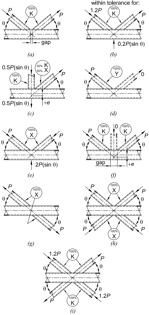
Figure description:
| Diagram | Connection Classification | Key Loading and Geometry Details |
|---|---|---|
| (a) | 100% K | Two angled braces () with balanced axial loads and a specified gap. |
| (b) | 100% K | Two angled braces () with loads and ; chord load .) |
| (c) | 100% K; 50% K / 50% X | Three braces (vertical and angled; chord and axial loads; eccentricity .) |
| (d) | 100% Y | One active brace at angle with load ; second brace is inactive (load 0.) |
| (e) | 100% X | Two compression braces at angle ; chord transverse load .) |
| (f) | 100% K | Two active angled braces, one inactive vertical brace; gap and eccentricity . |
| (g) | 100% X | Two braces crossing through the chord at angle with axial loads . |
| (h) | 100% X | Four compression braces at angle with axial loads . |
| (i) | 100% K | Four crossing braces at angle ; axial loads and . |
Fig. C-K1.1. Examples of HSS connection classification.
Specification for Structural Steel Buildings, August 1, 2022 AMERICAN INSTITUTE OF STEEL CONSTRUCTION
K-connections. The effective width parameter has been derived from research on transverse plate-to-HSS connections (Davies and Packer, 1982), and the coefficient of 10 in the calculation of the effective width, and , includes a partial safety factor reduction of 1.125 to address the sudden nature of the failure that can occur in some cases (Wardenier et al., 1981).
Uneven load distributions occur for other conditions as well. The flange local bend- ing check, addressed in Section J10.1, was originally intended so that the flange is thick enough to limit the unevenness of the stress to prevent weld fracture. Sections that are not sufficiently thick are reinforced. Generally, it is not practical to reinforce HSS members, so this option is not addressed in the Specification. Figure C-K1.3 illustrates the uneven load concept.
Section J4 addresses the strength of affected elements in tension, compression, flexure, and shear. When performing these checks for connections that deliver transverse load to rectangular HSS, the uneven load distribution described above can generally be accounted for relative to the branch member as shown in Table C-K1.1. The equation for , the effective width for transverse plates and the transverse elements of
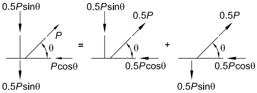
Figure description:
Fig. C-K1.2. Checking of K-connection with imbalanced branch member loads.
The diagram illustrates the superposition of forces in a K-connection:
- Left (Resultant State: Shows a branch member with axial load at angle , a vertical transverse load of (top and bottom, and a horizontal load of .
- Equals (= Sum of Two Components:
- Center Diagram: Branch member at angle with axial load , a vertical transverse load of , and a horizontal load of .
- Right Diagram: Branch member at angle with axial load , a downward vertical load of , and a horizontal load of .
Fig. C-K1.2. Checking of K-connection with imbalanced branch member loads.
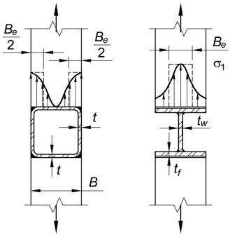
Figure description:
Key Information from Fig. C-K1.3:
-
Left Diagram (HSS Member:
- Structure: Hollow Structural Section (rectangular/square tube.
- Geometric Parameters: Member width , wall thickness .
- Effective Width (: Distributed as at each side of the member.
- Stress Distribution: Non-uniform "m-shaped" curve with peak stresses concentrated at the corners/outer edges.
-
Right Diagram (Wide-Flange Member:
- Structure: I-shaped cross-section.
- Geometric Parameters: Flange thickness , web thickness .
- Effective Width (: Concentrated width centered over the web.
- Stress Distribution (: Bell-shaped curve with peak stress concentrated at the center, aligned with the web.
-
Common Elements: Both diagrams illustrate elastic uneven stress distributions under axial tension, showing how effective width ( models the concentration of stress relative to the member's geometry.
Fig. C-K1.3. Elastic uneven stress distributions in HSS and wide-flange members.
Table C-K1.1 Effective Section Properties Due to Uneven Stresses
| Condition | Effective Section | Yielding |
|---|---|---|
| [Diagram] | Aeb = Betb | Tension or Compression Yielding Rn = FybAeb (Punching) Shear Yielding Rn = 0.6Fyt(2tb + 2Bep) |
| [Diagram] - Not present for T- or Y-connection | Aeb = (Be + Hb⁄Bb + Hb) Ab | Tension or Compression Yielding Rn = FybAeb (Punching) Shear Yielding Rn = 0.6Fyt(2Hb + 2Bep) |
| Branch(es) under In-Plane Bending T- and Cross-Connections [Diagram] - Not present for T-connection | Zeb = Zb (1 - Be⁄Bb) BbHbtb | Tension or Compression Yielding Mn = FybZeb (Punching) Shear Yielding Mn = 0.6Fyt x (2tb + Hb) (Hb⁄2) |
| Branch(es) under Out-of-Plane Bending T- and Cross-Connections [Diagram] | Zeb = Zb - 0.5 (1 - Be⁄Bb)2 Bb2tb | Tension or Compression Yielding Mn = FybZeb (Punching) Shear Yielding Mn = 0.6Fyt(2tb + 2Hb) x (Bb - tb) |
rectangular HSS branches, is empirically derived (Rolloos, 1969; Wardenier et al., 1981; Davies and Packer, 1982).
For simplicity, the punching shear equations for the in-plane and out-of-plane moment conditions conservatively neglect the effective width, . When the brace is beveled relative to the chord, the punching shear strengths can be adjusted to be consistent with the actual geometry.
When the branch (plate or HSS) width exceeds 85% of the connecting chord width, the transverse force from the branch can be assumed to be transferred predominately from the branch to the sidewalls of the chord. In such cases, the limit states associated with concentrated forces on the webs of I-sections, web local yielding (Section J10.2), web local crippling (Section J10.3), and web compression buckling (Section J10.5) can be used to determine the strength of the sidewalls of the chord.
When the branch (plate or HSS) width is less than 85% of the connecting chord width, the transverse force from the branch must pass through the face of the chord to be delivered to the sidewalls. Bending and shear on the chord face must be checked.
An analytical yield-line solution for flexure of the connecting chord face serves to limit connection deformations and is known to be well below the ultimate connection strength. A resistance factor, , of 1.00 or a safety factor, , of 1.50 is thus appropriate. When the branch width exceeds of the chord width, a yield-line failure mechanism will result in a noncritical connection capacity.
Punching shear can be based on the effective punching shear perimeter around the branch considering the effective width from Section K1.2 with the total branch perimeter being an upper limit on this length.
K1.3 Chord-Stress Interaction Parameter
, the chord-stress interaction parameter, is provided in Section K1.3 as it is a general parameter that applies to various connection configurations. Previous interaction equations for rectangular HSS main members (chords) could result in a chord-stress interaction parameter less than zero for some extreme conditions. A lower limit of 0.4 is imposed on the calculation to prevent such results in practice. This value is derived by assuming full utilization of the chord in Equation K1-3, which is believed to provide conservative results for both rectangular and round HSS configurations. The equations for are based on empirical results and will produce lower values for HSS-to-HSS connections with small width ratios, , than for longitudinal plate, with width ratios that are essentially zero. There is no theoretical model that explains these results. The discrepancy is likely the result of inconsistent consideration of factors other than connection strength in the empirical equations by various researchers and organizations.
The user of this Specification is advised that the use of HSS-to-HSS connections with small width ratios results in low strengths and inefficient designs. The stiffness of such connections will also tend to be quite low and may result in unserviceable performance even when sufficient strength exists.
K1.4 End Distance
Connection available strengths in Chapters J and K assume a main member with sufficient end distances, , on both sides of the connection. Equations in Section K1.4 provide limits to how close a branch or plate can be connected to the end of the chord. When a branch or plate is connected near to the end of a chord, there is not enough length to develop the typically assumed yield line patterns. A modified yield line pattern can be shown to develop an equal strength if the branch or plate is at least a distance equal to the minimum end distance, , from the chord end. Where the end distance is less than the limit, a cap plate or a reduction in the resistance are commonly accepted alternatives. The reduction in resistance may not be a linear proportion of the end distance. When the branch or plate is closer to the unreinforced end of a chord than indicated, the strengths predicted can conservatively be reduced by 50%. The branch member or plate supplying the load must have sufficient lateral restraint. Consideration of the minimum end distance, , has been added to the Specification in accordance with recent studies (Bu and Packer, 2019).