C-K3K3 HSS-to-HSS truss connections
PDF page 601 · AISC 360-22
A 30° minimum branch angle is a practical limit for good fabrication. Smaller branch angles are possible, but prior agreement with the fabricator should be made.
The limits of applicability in Table K3.1A and Table K3.2A generally represent the parameter range over which the equations have been verified through experiments. The following limitations bear explanation.
The restriction on the minimum overlap is applied so that there is an adequate inter-connection of the branches to enable effective shear transfer from one branch to the other.
If the gap size in a gapped K- (or N-) connection as shown in Figure C-K1.1(a) becomes large and exceeds the value permitted by the eccentricity limit, the K-connection should be treated as two independent Y-connections. In cross-connections, such as Figure C-K1.1(e), where the branches are close together or overlapping, the combined “footprint” of the two branches can be taken as the loaded area on the chord member. In K-connections, such as Figure C-K1.1(d), where a branch has very little or no loading, the connection can be treated as a Y-connection, as shown.
The design of welded HSS connections is based on potential limit states that may arise for particular connection geometry and loading, which in turn, represent possible failure modes that may occur within prescribed limits of applicability. Some typical failure modes for truss-type connections, shown for rectangular HSS, are given in Figure C-K3.1.
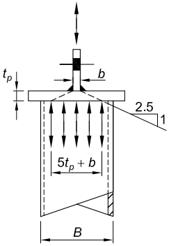
Figure description:
Key Information:
- Subject: Structural diagram illustrating load dispersion from a concentrated force through a cap plate into an HSS (Hollow Structural Section member.
- Key Components:
- Top Member: Width denoted as .
- Cap Plate: Thickness denoted as .
- Receiving Member (HSS: Overall width denoted as .
- Load Dispersion Geometry:
- The load disperses from the top member through the cap plate at a slope of 2.5:1 (horizontal to vertical.
- Effective Dispersion Width: Calculated as at the interface between the cap plate and the HSS member.
Fig. C-K2.2. Load dispersion from a concentrated force through a cap plate.
Connections in Tables K3.1 and K3.2 are for branches subjected to axial loading only. Two analysis methods that will result in branches with axial loads are as follows:
- (a) Pin-jointed analysis, or
- (b) Analysis using web members pin-connected to continuous chord members, as shown in Figure C-K3.2.
K3.1 Definitions of Parameters
Some parameters are defined in Figure C-K2.1.
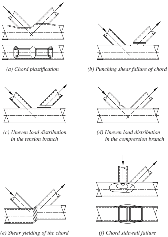
Figure description:
Fig. C-K3.1. Typical failure modes for HSS-to-HSS truss connections:
- (a Chord plastification: Localized yielding and deformation of the chord face where branches are attached.
- (b Punching shear failure of chord: A branch member shears through and punches out a section of the chord wall.
- (c Uneven load distribution in the tension branch: Stress concentration leading to localized failure at the tension branch-to-chord interface.
- (d Uneven load distribution in the compression branch: Local buckling or yielding of the compression branch near the connection.
- (e Shear yielding of the chord: Plastic shear deformation of the chord member's cross-section in the gap between branches.
- (f Chord sidewall failure: Yielding, crushing, or buckling of the vertical sidewalls of the chord member under concentrated loads.
Fig. C-K3.1. Typical failure modes for HSS-to-HSS truss connections.
K3.2 Round HSS
The wall slenderness limit for the compression branch is a restriction so that connection strength is not reduced by branch local buckling.
The minimum width ratio limit for gapped K-connections is based on Packer (2004), who showed that for width ratios less than 0.4, Equation K3-4 may be potentially unconservative when evaluated against proposed equations for the design of such connections by the American Petroleum Institute (API, 1993).
The restriction on the minimum gap size is stated so that adequate space is available to enable welding at the toes of the branches to be satisfactorily performed. The minimum gap limit is intended to restrict the development of excessive load concentration and reflects the limits of testing.
The restriction on the minimum overlap is applied so that there is an adequate inter-connection of the branches to enable effective shear transfer from one branch to the other.
The provisions given in Table K3.1 for T-, Y-, cross-, and K-connections are generally based, with the exception of the punching shear provision, on semi-empirical “characteristic strength” expressions that have a confidence of 95%, taking into account the variation in experimental test results as well as typical variations in mechanical and geometric properties. These “characteristic strength” expressions are then multiplied by resistance factors for LRFD or divided by safety factors for ASD to further allow for the relevant failure mode.
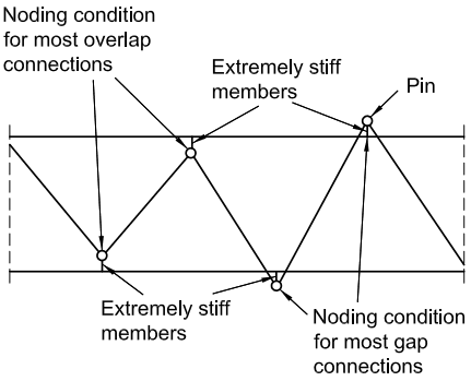
Figure description:
Key Entities and Information:
- Continuous Chord Members: Represented by the parallel horizontal lines.
- Web Members: Diagonal lines pin-connected to the chords.
- Pins: Circular nodes representing the joint connections between members.
- Extremely Stiff Members: Short vertical segments connecting pins to the chord centerlines or faces to model eccentricity.
- Overlap Connection Noding: Modeled with pins located within the chord depth.
- Gap Connection Noding: Modeled with pins located outside or offset from the chord centerline.
- Modeling Assumption: Illustrates how to idealize truss connections for structural analysis (Fig. C-K3.2.
Fig. C-K3.2. Modeling assumption using web members pin-connected to continuous chord members.
In the case of the chord plastification failure mode, and , whereas in the case of punching shear, and . For the case of punching shear, (equivalent to ) is used in many recommendations or specifications, for example, IIW (1989), Wardenier et al. (1991), and Packer and Henderson (1997), to reflect the large degree of reserve strength beyond the analytical nominal strength expression, which is itself based on the shear yield (rather than ultimate) strength of the material. In this Specification, however, and are used to maintain consistency with the factors for similar failure modes in Table K3.2.
If the tensile strength, , were adopted as a basis for a punching shear rupture criterion, the accompanying would be 0.75 and would be 2.00 , as elsewhere in this Specification. Then, would yield a very similar value to , and in fact, the latter is even more conservative for HSS with specified nominal ratios less than 0.79 . Equation K3-1 need not be checked when because this is the physical limit at which the branch can punch into (or out of) the main tubular member.
With round HSS in axially loaded K-connections, the size of the compression branch dominates the determination of the connection strength. Hence, the term in Equation K3-4 pertains only to the compression branch and is not an average of the two branches. Thus, if one requires the connection strength expressed as a force in the tension branch, one can resolve the answer from Equation K3-4 into the direction of the tension branch, using Equation K3-5. That is, it is not necessary to repeat a calculation similar to Equation K3-4 with as the tension branch.
K3.3 Rectangular HSS
The restriction on the minimum gap ratio in Table K3.2A is modified from IIW (1989), according to Packer and Henderson (1997), to be more practical. The minimum gap size, g, is only specified so that adequate space is available to enable welding at the toes of the branches to be satisfactorily performed. The minimum gap limit is intended to restrict the development of excessive load concentration and reflects the limits of testing.
The limit state of punching shear, evident in Equation K3-8, is based on the effec- tive punching shear perimeter around the branch, with the total branch perimeter being an upper limit on this length. The term βeop in Equation K3-8 represents the chord face effective punching shear width ratio adjacent to one of the branch walls transverse to the chord axis. This beop term incorporates φ = 0.80 or Ω = 1.88. Applying to generally one dimension of the rectangular branch footprint, this was deemed to be similar to a global φ = 0.95 or Ω = 1.58 for the whole expression; therefore, this expression for punching shear appears in AWS (2015) with an overall φ = 0.95. This φ = 0.95 or Ω = 1.58 has been carried over to this Specification, and this topic is discussed further in Commentary Section K3.2. The limitation specified for Equation K3-8 in Table K3.2 indicates when this failure mode is either physi- cally impossible or noncritical. In particular, note that shear yielding is noncritical for square HSS branches.
For axially loaded, gapped K-connections, plastification of the chord connecting face under the “push-pull” action of the branches is by far the most prevalent and critical failure mode. Indeed, if all the HSS members are square, this failure mode is critical and Equation K3-7 is the only one to be checked. This formula for chord face plastification is a semi-empirical “characteristic strength” expression, which has a confidence of 95%, taking into account the variation in experimental test results as well as typical variations in mechanical and geometric properties. Equation K3-7 is then multiplied by a factor for LRFD or divided by an factor for ASD, to further allow for the failure mode and provide an appropriate safety margin. A reliability calibration (Packer et al., 1984) for this equation, using a database of 263 gapped K-connections and the exponential expression for the resistance factor (with a reliability index of 3.0 and a coefficient of variation of 0.55 ) derived a and a corresponding , while also imposing the parameter limits of validity. Because this failure mode dominates the test database, there is insufficient supporting test data to calibrate Equations K3-8 and K3-9.
For the limit state of shear yielding of the chord in the gap of gapped K-connections, Table K3.2 differs from international practice (IIW, 1989) by recommending application of another section of this Specification—Section G4. This limit state need only be checked if the chord member is rectangular, not square, and is also oriented such that the shorter wall of the chord section lies in the plane of the truss, hence providing a more critical chord shear condition due to the short “webs.” The axial force present in the gap region of the chord member may also have an influence on the shear strength of the chord sidewalls in the gap region.
For K-connections, the scope covers both gapped and overlapped connections. Note that the latter are generally more difficult and more expensive to fabricate than K-connections with a gap. However, an overlapped connection will, in general, produce a connection with a higher static strength and fatigue resistance, as well as a stiffer truss than its gapped connection counterpart.
For rectangular HSS meeting the limits of applicability in Table K3.2A, the sole failure mode to be considered for design of overlapped connections is the limit state of uneven load distribution in the branches, manifested by either local buckling of the compression branch or premature yield failure of the tension branch. The design procedure presumes that one branch is welded solely to the chord and hence only has a single cut at its end. This can be considered good practice and the “thru member” is termed the overlapped member. For partial overlaps of less than 100%, the other branch is then double-cut at its end and welded to both the thru branch as well as the chord.
The branch to be selected as the “thru” or overlapped member should be the one with the larger overall width. If both branches have the same width, the thicker branch should be the overlapped branch.
For a single failure mode to be controlling (and not have failure by one branch punching into or pulling out of the other branch, for example), limits are placed on various connection parameters, including the relative width and relative thickness of the two branches. The foregoing fabrication advice for rectangular HSS also pertains
to round HSS overlapped K-connections, but the latter involves more complicated profiling of the branch ends to provide good saddle fits.
Overlapped rectangular HSS K-connection strength calculations (Equations K3-10, K3-11, and K3-12) are performed initially just for the overlapping branch, regardless of whether it is in tension or compression, and then the resistance of the overlapped branch is determined from that. The equations for connection strength, expressed as a force in a branch, are based on the load-carrying contributions of the four sidewalls of the overlapping branch and follow the design recommendations of the International Institute of Welding (IIW, 1989; Packer and Henderson, 1997; AWS, 2015). The effective widths of overlapping branch member walls transverse to the chord, , depend on the flexibility of the surface on which they land, and are derived from plate-to-HSS effective width measurements (Rolloos, 1969; Wardenier et al., 1981; Davies and Packer, 1982).
The applicability of Equations K3-10, K3-11, and K3-12 depends on the amount of overlap, , where . It is important to note that is the projected length (or imaginary footprint) of the overlapping branch on the chord, even though it does not physically contact the chord. Also, is the overlap length measured along the connecting face of the chord beneath the two branches. This is illustrated in Figure C-K2.1.
A maximum overlap of 100% occurs when one branch sits completely on the other branch. In such cases, the overlapping branch is sometimes moved slightly up the overlapped branch so that the heel of the overlapping branch can be fillet welded to the face of the overlapped branch. If the connection is fabricated in this manner, an overlap slightly greater than 100% is created. In such cases, the connection strength for a rectangular HSS connection can be calculated by Equation K3-12 but with the term replaced by another term. Also, with regard to welding details, it has been found experimentally that it is permissible to just tack weld the “hidden toe” of the overlapped branch, providing that the components of the two branch member forces normal to the chord substantially balance each other and providing that the welds are designed for the yield capacity of the connected branch walls. The “hidden toe” should be fully welded to the chord if the normal components of the two branch forces differ by more than 20% or the welds to the branches are designed using an effective length approach. More discussion is provided in Commentary Section K5. If the components of the two branch forces normal to the chord do in fact differ significantly, the connection should also be checked for behavior as a T-, Y-, or cross-connection, using the combined footprint and the net force normal to the chord (see Figure C-K1.2).
For the design of round branches connecting to rectangular chords in T-, Y-, X-, and K-gapped connections under static loading, a conversion method can be used to check chord wall plastification if the branch to chord width ratio, , is less than 0.85 . Supported by Packer et al. (2007), the conversion involves the replacement of the round branch (or branches) of diameter by equivalent square branches of width and the same thickness; then the design rule for chord wall
plastification in rectangular HSS-to-rectangular HSS connections in Table K3.2 can be applied to round HSS-to-rectangular HSS connections. For round HSS-to-rectangular HSS K-overlapped connections, the conversion method can be used if the chord width ratio, , is less than 0.8 to check local yielding of the branch or branches due to uneven load distribution for . Many failure modes for HSS connections depend on the perimeter or cross-sectional area of the branch member, and both the perimeter and area of a round HSS, when compared to that of a square HSS, have a ratio of .