C-K2K2 Concentrated forces on HSS
PDF page 599 · AISC 360-22
Sections K2.2 and K2.3, although pertaining to all concentrated forces on HSS, are particularly oriented towards plate-to-HSS welded connections.
Wide-flange beam-to-HSS partially restrained moment connections can be modeled as a pair of transverse plates at the beam flanges, neglecting the effect of the web. The beam moment is thus produced by a force couple in the beam flanges. The connection flexural strength is then given by the plate-to-HSS connection strength multiplied by the distance between the beam flange centers.
K2.1 Definitions of Parameters
Some of the notation used in Chapter K is illustrated in Figure C-K2.1.
K2.2 Round HSS
The limits of applicability in Table K2.1A stem primarily from limitations on tests conducted to date.
K2.3 Rectangular HSS
When connecting single-plate shear connections to HSS columns, the AISC Steel Construction Manual (AISC, 2017) includes recommendations based on Sherman and Ales (1991) and Sherman (1995b, 1996), where a large number of simple framing connections between wide-flange beams and rectangular HSS columns are investigated, in which the load transferred was predominantly shear. A review of costs also showed that single-plate and single-angle connections were the most economical, with double-angle and fillet-welded tee connections being more expensive. Through-plate and flare-bevel welded tee connections were among the most expensive (Sherman, 1995b). Over a wide range of connections tested, only one limit state was identified for the rectangular HSS column: punching shear failure related to end rotation of the beam, when a thick shear plate was joined to a relatively thin-walled HSS. Prior to 2016, the available shear strength of the HSS wall was compared to the
available tensile strength of the plate. Because the check only applied to single-plate shear connections, it was removed from the Specification. A check was added to the AISC Manual that investigates punching shear of the HSS wall due to a beam end reaction applied eccentrically, with the eccentricity being the distance from the HSS wall to the center-of-gravity of the bolt group.
The strength of a square or rectangular HSS wall with load transferred through a cap plate (or the flange of a T-stub), as shown in Figure C-K2.2, can be calculated by considering the limit states of local yielding and local crippling. In general, the rectangular HSS could have dimensions of B × H, but the illustration shows the bearing length (or width), b, oriented for lateral load dispersion into the wall of dimension B. A conservative distribution slope can be assumed as 2.5:1 from each face of the tee web (Wardenier et al., 1991; Kitipornchai and Traves, 1989), which produces a dispersed load width of (5tp + b) relative to local yielding. If this is less than B, only the two sidewalls of dimension B are effective in resisting the load, and even they will both be only partially effective. If (5tp + b) ≥ B, all four walls of the rectangular HSS will be engaged, and all will be fully effective; however, the cap plate (or T-stub flange) must be sufficiently thick for this to happen. If the weld leg size is known, it is acceptable to assume load dispersion from the toes of the welds. Neglecting the effect of the weld is conservative. The same load disper- sion model as shown in Figure C-K2.2 can also be applied to round HSS-to-cap plate connections.
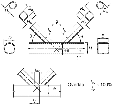
Figure description:
This image illustrates the standard notation for Hollow Structural Section (HSS truss connections, specifically K-connections.
Key Entities and Notation:
- Main Member (Chord:
- : Outer diameter (round HSS.
- : Overall width (rectangular HSS.
- : Overall height (rectangular HSS.
- : Design wall thickness.
- Branch Members:
- : Outer diameter.
- : Overall width.
- : Overall height.
- : Design wall thickness.
- : Angle between branch and chord.
- Connection Geometry:
- : Gap between branches measured along the chord face.
- : Eccentricity (positive if branches intersect above the chord centerline, negative if below.
- : Overlap length measured along the chord face.
- : Projected length of the overlapping branch on the chord face.
Mathematical Formula:
- Overlap Percentage:
Fig. C-K2.1. Common notation for HSS connections.
Specification for Structural Steel Buildings, August 1, 2022 AMERICAN INSTITUTE OF STEEL CONSTRUCTION
If a longitudinal plate-to-rectangular HSS connection is made by passing the plate through a slot in the HSS and then welding the plate to both the front and back HSS faces to form a “through-plate connection,” the nominal strength can be taken as equal to the sum of the yield-line strength of each wall (Kosteski and Packer, 2003).