C-D3D3 Effective net area
PDF page 414 · AISC 360-22
This section deals with the effect of shear lag, applicable to both welded and bolted tension members. Shear lag is a concept used to account for uneven stress distribution in connected members where some but not all of their elements (flange, web, leg, etc.) are connected. The reduction coefficient, , is applied to the net area, , of bolted members and to the gross area, , of welded members. As the length of the connection, , is increased, the shear lag effect diminishes. This concept is expressed empirically by the equation for . Using this expression to compute the effective area, the estimated strength of some 1,000 bolted and riveted connection test specimens, with few exceptions, correlated with observed test results within a scatter band of (Munse and Chesson, 1963). Subsequent research provides further justification for the current provisions (Easterling and Gonzales, 1993).
For any given profile and configuration of connected elements, is the perpendicular distance from the connection plane, or face of the member, to the centroid of the member section resisting the connection force, as shown in Figure C-D3.1. The length, , used in Table D3.1, is a function of the number of rows of fasteners or the length of weld. The length, , is illustrated as the distance, parallel to the line of force, between the first and last row of fasteners in a line for bolted connections. The number of bolts in a line, for the purpose of the determination of , is determined by the line with the maximum number of bolts in the connection. For staggered bolts, the out-to-out dimension is used for , as shown in Figure C-D3.2.
For tension members with connections similar to that shown in Figure C-D3.1, the distance from the force in the member to the shear plane of the connection must be determined. For the I-shaped member with bolts in the flanges as shown in Figure C-D3.1(a), the member is treated as two WT-shapes. Because the section shown is symmetric about the horizontal axis and that axis is also the plastic neutral axis, the first moment of the area above the plastic neutral axis is , where is the
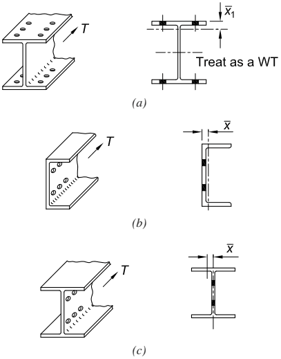
Figure description:
Fig. C-D3.1. Determination of for
-
Diagram (a: I-shaped member with flange bolts.
- Action: Treat as a WT-section.
- Dimension : Distance from the shear plane (outer flange face to the centroid of the equivalent WT-shape.
- Force: Tension ( applied along the member.
-
Diagram (b: Channel section with web bolts.
- Dimension : Distance from the shear plane (outer web face to the centroid of the channel.
- Force: Tension ( applied along the member.
-
Diagram (c: I-shaped member with web bolts.
- Dimension : Distance from the shear plane (web face to the centroid of the equivalent section half.
- Force: Tension ( applied along the member.
Fig. C-D3.1. Determination of for U.
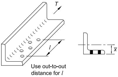
Figure description:
Structural Steel Angle Member Details
-
Key Entities:
- L-shaped angle member: Shown in perspective and cross-section views.
- Staggered bolt holes: Located on one leg of the angle.
- Tensile force (: Applied longitudinally to the member.
-
Dimensions for Shear Lag Factor ( Determination:
- (Connection Length: Measured as the "out-to-out" longitudinal distance between the centers of the first and last bolt holes.
- (Eccentricity: The distance from the connected face of the angle to its centroidal axis, shown in the cross-sectional view.
Fig. C-D3.2. Determination of for U of bolted connections with staggered holes.
plastic section modulus of the entire section, . The area above the plastic neutral axis is ; therefore, by definition . Thus, for use in calculating , . For the I-shaped member with bolts in the web as shown in Figure C-D3.1(c), the shape is treated as two channels and the shear plane is assumed to be at the web centerline. Using the definitions just discussed, but related now to the y-axis, yields . Note that the plastic neutral axis must be an axis of symmetry for this relationship to apply. Thus, it cannot be used for the case shown in Figure C-D3.1(b) where would simply be determined from the properties of a channel.
There is insufficient data for establishing a value of if all lines have only one bolt, but it is probably conservative to use equal to the net area of the connected element. The limit states of block shear (Section J4.3) and bearing and tearout (Section J3.11), which must be checked, will probably control the design. Historically, the minimum length of welds in end connections has not been less than the perpendicular distance between the welds. This practice dates to the 1946 AISC Specification (AISC, 1946). Though no longer a requirement, this practice is still reasonable.
The ratio of the area of the connected element to the gross area is a reasonable lower bound for and allows for cases where the calculated based on is very small or nonexistent, such as when a single bolt per gage line is used and .
The effect of connection eccentricity is a function of connection and member stiffness and may sometimes need to be considered in the design of the tension connection or member. Historically, engineers have neglected the effect of eccentricity in both the member and the connection when designing tension-only bracing. In Cases 1a and 1b shown in Figure C-D3.3, the length of the connection required to resist the axial loads will usually reduce the applied axial load on the bolts to a negligible value. For Case 2, the flexibility of the member and the connections will allow the member to deform such that the resulting eccentricity is relieved to a considerable extent.
For welded connections, is the length of the weld parallel to the line of force as shown in Figure C-D3.4 for longitudinal and longitudinal plus transverse welds. For welds with unequal lengths, use the average length.
End connections for HSS in tension are commonly made by welding around the perimeter of the HSS; in this case, there is no shear lag or reduction in the gross area. Alternatively, an end connection with gusset plates can be used. Single gusset plates may be welded in longitudinal slots that are located at the centerline of the cross section. Welding around the end of the gusset plate may be omitted for statically loaded connections to prevent possible undercutting of the gusset and having to bridge the gap at the end of the slot. In such cases, the net area at the end of the slot is the critical area as illustrated in Figure C-D3.5. Alternatively, a pair of gusset plates can be welded to opposite sides of a rectangular HSS with flare bevel groove welds with no reduction in the gross area.
The shear lag factors given in Cases 7 and 8 of Table D3.1 are given as alternate values to the value determined from given for Case 2 in Table D3.1. It is permissible to use the larger of the two values.
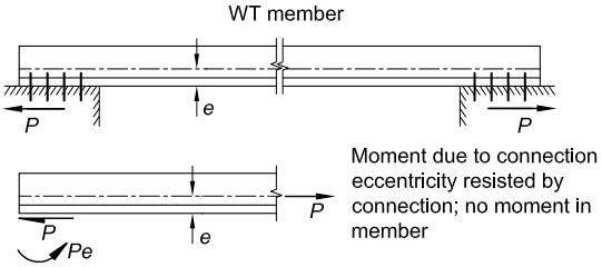
Figure description:
Key Information:
- Entity: WT member (T-shaped structural beam.
- Scenario (Case 1a: End rotation is restrained by connections to rigid abutments.
- Loading: Tension force applied with an eccentricity from the member's neutral axis.
- Mechanics: The moment generated by eccentricity ( is resisted entirely by the connection to the abutment.
- Result: There is no bending moment transferred into the span of the member.
(a) Case 1a. End rotation restrained by connection to rigid abutments
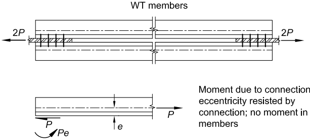
Figure description:
Key Information:
- Entities: WT (structural T-section members under tension.
- Forces and Moments:
- Total tension force of applied at connection ends.
- Connection eccentricity ( creates a localized moment (.
- Structural Behavior:
- The diagram illustrates cases where end rotation is restrained (by rigid abutments or symmetry.
- The moment generated by eccentricity is resisted entirely by the connection.
- No resultant moment is transferred into the main body of the WT members.
(b) Case 1b. End rotation restrained by symmetry
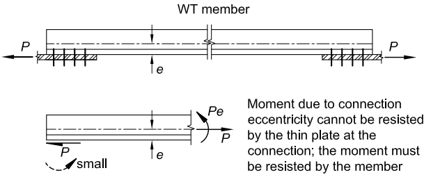
Figure description:
- Subject: Structural analysis of a WT member under tensile load .
- Key Entities:
- WT member: T-shaped structural steel member.
- Connection: Eccentric connection with eccentricity between the centroid and the load line.
- Force (: Applied tensile load.
- Moment (: Internal moment caused by the load eccentricity.
- Key Mechanics:
- The diagram illustrates a case where end rotation is not restrained due to connection to a thin plate.
- Constraint: The thin plate at the connection cannot resist the eccentric moment.
- Consequence: The member itself must resist the full eccentric moment (.
- Result: Indicated "small" rotation at the connection point.
(c) Case 2. End rotation not restrained—connection to thin plate
Fig. C-D3.3. The effect of connection restraint on eccentricity.