C-D6D6 Eyebars
PDF page 419 · AISC 360-22
Forged eyebars have generally been replaced by pin-connected plates or eyebars thermally cut from plates. Provisions for the proportioning of eyebars contained in this Specification are based upon standards evolved from long experience with
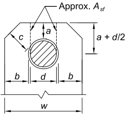
Figure description:
Key Entities and Information:
- Subject: Structural diagram of a pin-connected plate or eyebar end.
- Geometric Parameters:
- : Diameter of the pin hole.
- : Net width of the plate on each side of the pin hole.
- : Edge distance from the top of the pin hole to the plate edge.
- : Total width of the plate (.
- : Diagonal distance from the pin hole to the chamfered corner.
- : Total distance from the pin center to the top edge.
- Notations:
- Approx. : Indicates the approximate shear failure area, shown by vertical dashed lines extending from the pin hole to the edge.
- Hatched Circle: Represents the pin or the opening for the pin.
Dimensional Requirements
where in.
Fig. C-D5.1. Dimensional requirements for pin-connected members.
forged eyebars. Through extensive destructive testing, eyebars have been found to provide balanced designs when they are thermally cut instead of forged. The more conservative rules for pin-connected members of nonuniform cross section and for members not having enlarged "circular" heads are likewise based on the results of experimental research (Johnston, 1939).
Stockier proportions are required for eyebars fabricated from steel having a specified minimum yield stress greater than 70 ksi (485 MPa) to eliminate any possibility of their “dishing” under the higher design stress.
D6.1 Tensile Strength
The tensile strength of eyebars is determined as for general tension members, except that, for calculation purposes, the width of the body of the eyebar is limited to eight times its thickness.
D6.2 Dimensional Requirements
Dimensional limitations for eyebars are illustrated in Figure C-D6.1. Adherence to these limits assures that the controlling limit state will be tensile yielding of the body; thus, additional limit state checks are unnecessary.
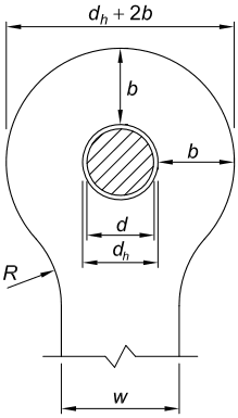
Figure description:
Key Information:
- Subject: Dimensional layout and limitations for an eyebar (Figure C-D6.1.
- Geometric Parameters:
- : Width of the eyebar body.
- : Diameter of the pin.
- : Diameter of the pin hole.
- : Net width of the eyebar head on each side of the hole.
- : Total overall width of the eyebar head.
- : Transition radius from the head to the body.
- Purpose: Provides a standard for eyebar dimensions to ensure that tensile yielding of the body is the controlling limit state.
Dimensional Requirements
-
in. (13 mm) (Exception is provided in Section D6.2(e))
-
(For calculation purposes only)
- in.
- (Upper limit is for calculation
purposes only).
Fig. C-D6.1. Dimensional limitations for eyebars.