C-D5D5 Pin-connected members
PDF page 418 · AISC 360-22
Pin-connected members are occasionally used as tension members with very large dead loads. Pin-connected members are not recommended when there is sufficient variation in live loading to cause wearing of the pins in the holes. The dimensional requirements presented in Section D5.2 must be met to provide for the proper functioning of the pin.
D5.1 Tensile Strength
The tensile strength requirements for pin-connected members use the same and values as elsewhere in this Specification for similar limit states. However, the definitions of effective net area for tension and shear are different.
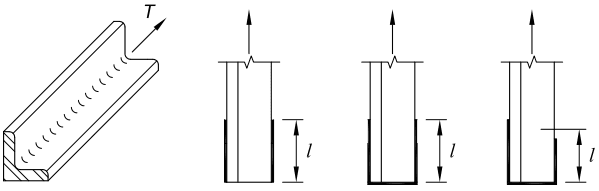
Figure description:
- Entities: Steel angle member, tensile force (, longitudinal welds, transverse welds.
- Purpose: Illustrates the determination of weld length ( used to calculate the shear lag factor (.
- Key Details:
- Diagram 1: Isometric view showing an angle member under tension ( with longitudinal welds.
- Diagram 2: Longitudinal welds only; is the length of the longitudinal weld.
- Diagram 3: Combined longitudinal and transverse welds; is the length of the longitudinal weld.
- Diagram 4: Unequal longitudinal welds with a transverse weld; is defined as the average length of the longitudinal welds.
Fig. C-D3.4. Determination of for calculation of for connections with longitudinal and transverse welds.
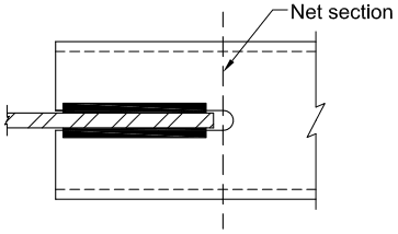
Figure description:
Key Information:
- Subject: Structural diagram for determining the net area of a connection through a slot.
- Entities:
- Main Member: Structural element (likely a hollow section with a longitudinal slot.
- Gusset Plate: A single cross-hatched plate inserted into the slot.
- Welds: Represented by solid black rectangles, joining the gusset plate to the member.
- Net Section: Indicated by a vertical dashed line passing through the end of the slot, marking the plane where net area is calculated.
Fig. C-D3.5. Net area through slot for a single gusset plate.
D5.2 Dimensional Requirements
The capacity of pin-connected members and their connections involve complex stress distributions and various failure modes. Dimensional limitations have been imposed on these members to limit the modes that must be checked. In the past, these dimensional limitations limited the diameter of the pin hole to no more than in. (1 mm) larger than the diameter of the pin when the member is expected to provide for relative movement of the connected part under full load. This small clearance can lead to erection and other issues, especially with larger diameter pins. Duerr (2006) summarized the theory and results of past test programs on pin-connected members. Based on this research, a 3-in.- (75-mm-) diameter pin utilizing a -in.- (2-mm-) diameter oversized hole and a reduction factor, , would be a conservative design. Larger pins with the same clearance would have a value approaching 1.0 . A pin hole oversize of in. (2 mm) is allowed for pins with a diameter of 3 in. (75 mm) or larger to ease clearance issues, provided the design values are multiplied by 0.95 to account for the worst case of this correction factor. Pins larger than 3 in. (75 mm) in diameter with this -in.- (2-mm-) diameter hole clearance would theoretically require less of an adjustment to their capacity, but that level of precision is not included currently in this Specification. Hole diameters larger than pin diameter plus in. (2 mm) are not currently allowed due to the implications of additional structural movement that could occur because of the increased hole size and the absence of clamping force from the pin connection—unlike what would exist with a bolted connection. The engineer of record should determine if the additional clearance would negatively impact the structural design.
Dimensional requirements for pin-connected members are illustrated in Figure C-D5.1.