C-J1J1 General provisions
PDF page 541 · AISC 360-22
J1.1 Design Basis
In the absence of defined design loads, a minimum design load should be considered. Historically, a value of 10 kips (44 kN) for LRFD and 6 kips (27 kN) for ASD have been used as reasonable values. For smaller elements such as lacing, sag rods, girts, or similar small members, a load more appropriate to the size and use of the part should be used. Both design requirements and construction loads should be considered when specifying minimum loads for connections.
J1.2 Simple Connections
Simple connections are considered in this section and Section B3.4a. In Section B3.4a, simple connections are defined in an idealized manner for the purpose of analysis. The assumptions made in the analysis determine the outcome of the analysis that serves as the basis for design; for connections, that means the force and deformation demands that the connection must resist. This section focuses on the actual proportioning of the connection elements to achieve the required resistance. Thus, Section B3.4a establishes the modeling assumptions that determine the design forces and deformations for use in Section J1.2.
This section and Section B3.4a are not mutually exclusive. If a “simple” connection is assumed for analysis, the actual connection, as finally designed, must perform consistent with that assumption. A simple connection must be able to meet the required rotation and must not introduce strength and stiffness that significantly alters the rotational response.
J1.3 Moment Connections
Two types of moment connections are defined in Section B3.4b: fully restrained (FR) and partially restrained (PR). FR moment connections must have sufficient strength and stiffness to transfer moment and maintain the angle between connected members. PR moment connections are designed to transfer moments but also allow rotation between connected members as the loads are resisted. The response characteristics of a PR connection must be documented in the technical literature or established by analytical or experimental means. The component elements of a PR connection must have sufficient strength, stiffness, and deformation capacity to satisfy the design assumptions.
J1.4 Compression Members with Bearing Joints
The provisions in Section J1.4(b), for compression members other than columns finished to bear, are intended to account for member out-of-straightness and also to provide a degree of robustness in the structure to resist unintended or accidental lateral loadings that may not have been considered explicitly in the design.
A provision analogous to that in Section J1.4(b)(1), requiring that splice materials and connectors have an available strength of at least 50% of the required compressive strength, has been in the AISC Specification since 1946 (AISC, 1946). The current Specification clarifies this requirement by stating that the force for proportioning the splice materials and connectors is a tensile force. This avoids uncertainty as to how to handle situations where compression on the connection imposes no force on the connectors.
Proportioning the splice materials and connectors for 50% of the required member strength is simple, but can be very conservative. In Section J1.4(b)(2), the Specification offers an alternative that addresses directly the design intent of these provisions. The lateral load of 2% of the required compressive strength of the member simulates the effect of a kink at the splice caused by an end finished slightly out-of-square or other construction condition. Proportioning the connection for the resulting moment and shear also provides a degree of robustness in the structure.
J1.5 Splices in Heavy Sections
Solidified but still hot weld metal contracts significantly as it cools to ambient temperature. Shrinkage of large groove welds between elements that are not free to move so as to accommodate the shrinkage causes strains in the material adjacent to the weld that can exceed the yield point strain. In thick material, the weld shrinkage is restrained in the thickness direction and in the width and length directions causing triaxial stresses to develop that may inhibit the ability to deform in a ductile manner. Under these conditions, the possibility of brittle fracture increases.
The web-to-flange intersection and the web center of heavy hot-rolled shapes, as well as the interior portions of heavy plates, may contain a coarser grain structure and/or lower notch toughness than other areas of these products.
When splicing hot-rolled shapes with flange thickness exceeding 2 in. (50 mm) or heavy welded built-up members, these potentially harmful weld shrinkage strains can be avoided by using bolted splices or fillet-welded lap splices as shown in Figure C-J1.1, or splices that combine a welded and bolted detail. Details and techniques that perform well for materials of modest thickness usually must be changed or supplemented by more demanding requirements when welding thick material.
The provisions of AWS D1.1/D1.1M (AWS, 2020) are minimum requirements that apply to most structural welding situations. However, when designing and fabricating welded splices of hot-rolled shapes with flange thicknesses exceeding 2 in. (50 mm) and similar built-up cross sections, special consideration must be given to all aspects of the welded splice detail:
- (a) Notch-toughness requirements are required to be specified for tension members as discussed in Commentary Section A3.1d.
- (b) Generously sized weld access holes, as specified in Section J1.6, are required to provide increased relief from concentrated weld shrinkage strains to avoid close juncture of welds in orthogonal directions and to provide adequate clearance for the exercise of high-quality workmanship in hole preparation, welding, and for ease of inspection.
- (c) Preheating for thermal cutting is required to minimize the formation of a hard surface layer. See Section M2.2.
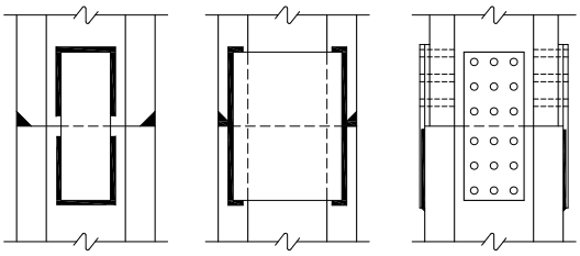
Figure description:
Key Information:
- Subject: Structural steel splice configurations designed to minimize weld restraint tensile stresses.
- Splice Type 1 (Left/Middle: Welded connections featuring groove welds (indicated by solid triangles and specific internal geometries to manage stress.
- Splice Type 2 (Right: A bolted splice utilizing a large splice plate secured with multiple bolts and partial-height welding on the sides.
- Components: Vertical structural members joined at a horizontal splice line, utilizing a combination of welding, bolting, and internal preparation to distribute loads.
Fig. C-J1.1. Alternative splices that minimize weld restraint tensile stresses.
(d) Grinding of copes and weld access holes to bright metal to remove the hard surface layer is required.
In addition to tension splices of truss chord members and tension flanges of flexural members, other joints fabricated from heavy sections subjected to tension should be given special consideration during design and fabrication.
Alternative details that do not generate shrinkage strains can be used. In connections where the forces transferred approach the member strength, directly welded groove joints may still be the most effective choice.
Until 1999, the Specification mandated that backing bars and weld tabs be removed from all splices of heavy sections. These requirements were deliberately removed, being judged unnecessary and, in some situations, potentially resulting in more harm than good. This Specification still permits the engineer of record to specify their removal when this is judged appropriate. The previous requirement for the removal of backing bars necessitated, in some situations, that such operations be performed out-of-position; that is, the welding required to restore the backgouged area had to be applied in the overhead position. This may necessitate different equipment for gaining access, different welding equipment, processes and procedures, and other practical constraints. When box sections made of plate are spliced, access to the interior side, which is necessary for backing removal, is typically impossible.
Weld tabs that are left in place on splices act as “short attachments” and attract little stress. Even though it is acknowledged that weld tabs might contain regions of inferior quality weld metal, the stress concentration effect is minimized because little stress is conducted through the attachment.
Previous editions of this Specification required magnetic particle or dye-penetrant inspection of thermally cut weld access holes for splices in heavy sections. This requirement was deliberately removed as anecdotal evidence suggested this inspection was not necessary because cracks from thermal cutting rarely occurred when the other Specification requirements were met. The previously prescribed magnetic particle testing or penetrant testing was replaced in Table N5.4-3 with a requirement for visual inspection of weld access holes after welding.
J1.6 Weld Access Holes
Weld access holes are frequently required in the fabrication of structural components. The geometry of these structural details can affect the components' performance. The size and shape of beam copes and weld access holes can have a significant effect on the ease of depositing sound weld metal, the ability to conduct nondestructive examinations, and the magnitude of the stresses at the geometric discontinuities produced by these details.
Weld access holes used to facilitate welding operations are required to have a minimum length from the toe of the weld preparation equal to the greater of 1.5 times the thickness of the material in which the hole is made or 1½ in. (38 mm) as shown in Figure C-J1.2. This minimum length is expected to accommodate a significant amount of the weld shrinkage strains at the web-to-flange intersection.
The height of the weld access hole must provide sufficient clearance for ease of welding and inspection and must be large enough to allow the welder to deposit sound weld metal through and beyond the web. A weld access hole height equal to 1.0 times the thickness of the material with the access hole, but not less than 3/4 in. (19 mm), has been judged to satisfy these welding and inspection requirements. The height of the weld access hole need not exceed 2 in. (50 mm).
The geometry of the reentrant corner between the web and the flange determines the level of stress concentration at that location. A 90° reentrant corner having a very small radius produces a very high stress concentration that may lead to rupture of the flange. Consequently, to minimize the stress concentration at this location, the edge of the web is sloped or curved from the surface of the flange to the reentrant surface of the weld access hole.
Stress concentrations along the perimeter of weld access holes also can affect the performance of the joint. Consequently, weld access holes are required to be free of stress raisers such as notches and gouges. The nondestructive testing (NDT) requirement of access holes in earlier editions of the Specification has been removed in response to reports that these examinations had revealed no defects.
Stress concentrations at web-to-flange intersections of built-up shapes can be decreased by terminating the weld away from the access hole. Thus, for built-up shapes
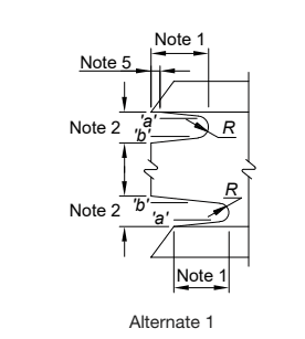
Figure description:
Title: Alternate 1
Subject: Technical drawing of a built-up shape showing weld termination and access hole dimensions at a web-to-flange intersection.
Key Entities:
- Note 1: Horizontal length dimension of the access hole cutout.
- Note 2: Vertical height dimension of the cutout.
- Note 5: Horizontal offset distance for the start of the cutout.
- R: Radius of the curved internal corners of the access hole.
- 'a' and 'b': Specific reference points marking the boundaries of the cut sections.
- Structural Elements: Flanges (horizontal and web (vertical sections.
Purpose: Illustrates a geometry designed to decrease stress concentrations by terminating welds away from the access hole.
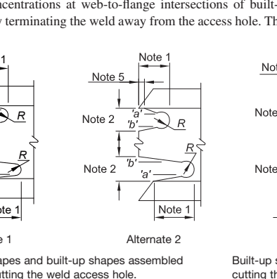
Figure description:
This image contains technical engineering diagrams for weld access holes in built-up shapes. Key entities and details include:
- Alternate 2 Diagram: Shows a specific configuration for weld access holes at web-to-flange intersections.
- Radius (R: Indicated for the curved portions of the access holes.
- Labels 'a' and 'b': Identify specific points or surfaces within the access hole geometry.
- Annotations:
- Note 1: Specifies horizontal dimensions for the length of the opening.
- Note 2: Specifies vertical dimensions for the depth/height of the opening.
- Note 5: Indicates a specific measurement or clearance at the weld termination point.
- Physical Features: Illustrates the intersection of vertical web and horizontal flange elements with a cut-out to facilitate welding.
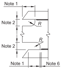
Figure description:
Technical diagram illustrating design specifications with the following annotations:
- Note 1: Horizontal dimension for the chamfered edge at both top and bottom.
- Note 2: Vertical dimension for the opening/gap height on both upper and lower sections.
- Note 6: Small horizontal offset or thickness dimension at the bottom.
- R: Radius of the curved inner corners.
- Visual Features: Section cut symbols (squiggly lines indicating a continuation of the part. Thickened lines represent specific surface treatments or coatings.
Alternate 1
Alternate 2
Alternate 3
Rolled shapes and built-up shapes assembled prior to cutting the weld access hole.
Built-up shapes assembled after cutting the weld access hole.
Notes: These are typical details for joints welded from one side against steel backing. Alternative details are discussed in the Commentary text.
- Length: Greater of 1.5tw or 1½ in. (38 mm)
- Height: Greater of 1.0tw or 3/4 in. (19 mm), but need not exceed 2 in. (50 mm)
- R: 3/8 in. (10 mm) min. Grind the thermally cut surfaces of weld access holes in heavy shapes as defined in Sections A3.1d and A3.1e.
- Slope ‘a’ forms a transition from the web to the flange. Slope ‘b’ may be horizontal.
- The bottom of the top flange is to be contoured to permit the tight fit of backing bars where they are to be used.
- The web-to-flange weld of built-up members is to be held back a distance of at least the weld size from the edge of the access hole.
Fig. C-J1.2. Weld access hole geometry.
with fillet welds or partial-joint-penetration groove welds that join the web to the flange, the weld access hole may terminate perpendicular to the flange, provided that the weld is terminated a distance equal to or greater than one weld size away from the access hole.
J1.7 Placement of Welds and Bolts
Slight eccentricities between the gravity axis of single- and double-angle members and the center of gravity of connecting bolts or rivets have long been ignored as having negligible effect on the static strength of such members. Tests have shown that similar practice is warranted in the case of welded members in statically loaded structures (Gibson and Wake, 1942). However, the fatigue life of eccentrically loaded welded angles has been shown to be very short (Klöppel and Seeger, 1964). Notches at the roots of fillet welds are harmful when alternating tensile stresses are normal to the axis of the weld, as could occur due to bending when axial cyclic loading is applied to angles with end welds not balanced about the neutral axis. Accordingly, balanced welds are required when such members are subjected to cyclic loading as shown in Figure C-J1.3.
J1.8 Bolts in Combination with Welds
As in previous editions, this Specification does not permit bolts or rivets to share the load with welds except for conditions where shear is resisted at the faying surface. In joints where the strength is based on the strength of bolts and welds acting together, the compatibility of deformations of the various components of the connection at the ultimate load level are important factors in determining the connection strength. Physical tests (Kulak and Grondin, 2003) and finite element models (Shi et al., 2011) have shown that bolts designed as part of a slip-critical connection and properly tightened according to the requirements for a slip-critical connection can share the load with longitudinal fillet welds, provided a reasonable proportion of the load is carried by each. The limits established are 50% minimum for the welds and 33% minimum for the high-strength bolts. The strength of transverse welds is not permitted to be included with the strength of bolts because these welds have less ductility. The provisions of this section are generally intended to be applied in cases where retrofit
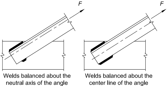
Figure description:
Key Information:
- Subject: Structural connection diagrams illustrating "Balanced welds" for an angle member under tension force (.
- Left Diagram: "Welds balanced about the neutral axis of the angle." Fillet welds are unequal in length, distributed to align the center of resistance with the eccentric neutral axis.
- Right Diagram: "Welds balanced about the center line of the angle." Fillet welds are shown as equal in length, centered on the physical centerline of the member.
- Key Entities:
- Angle Member: Structural component subjected to axial load.
- Gusset Plate: Base plate to which the angle is welded.
- Fillet Welds: Black rectangular indicators representing the welded connection.
- Force (: Tensile load applied along the member axis.
Fig. C-J1.3. Balanced welds.
Specification for Structural Steel Buildings, August 1, 2022 AMERICAN INSTITUTE OF STEEL CONSTRUCTION
work is required to accommodate higher design loads, or cases where the mean slip coefficient in the field may not have complied with the value assumed in the design. Special testing is required according to Appendix A of the RCSC Specification for Structural Joints Using High-Strength Bolts (RCSC, 2020) in such cases to validate the value of the slip coefficient, , used in the final retrofitted design.
The intent of this Specification, as prescribed in the second paragraph of this section, is that the combined joint will provide the required strength just prior to when the welds fracture, which defines the ultimate load level. The ultimate load is defined by the capacity of the welds and the slip resistance from the bolt pretension clamping force. No additional bearing or tearout capacity check is required. The use of a single resistance factor, , or safety factor, , on the nominal strength of the bolts and welds combined is intended to improve the reliability of the connection compared to the use of the higher resistance factor, , and lower safety factor, , permitted for standard holes in slip-critical bolted connections alone. For existing connections with high-strength bolts originally tightened by other methods than turn-of-nut, an additional turn for ASTM F3125/F3125M Grades A325 or A325M and turn for Grades A490 or A490M bolts would allow the bolts to be considered pretensioned by turn-of-nut relative to this section. Over-rotation of a bolt is not cause for rejection per the RCSC Specification. The additional rotation may occasionally result in bolt rupture, which will occur at the time the bolts are rotated. Broken bolts can be replaced with equivalent bolts installed using the turn-of-nut method. Note that the connection strength need not be taken as less than the strength of the bolts alone or the strength of the welds alone. The heat of welding near bolts will not alter the mechanical properties of the bolts.
The restrictions on bolts in combination with welds do not apply to typical bolted and welded beam-to-girder and beam-to-column connections, and other comparable connections where the bolts and welds are used on separate faying surfaces (Kulak et al., 1987).
J1.10 High-Strength Bolts in Combination with Existing Rivets
When high-strength bolts are used in combination with rivets, the ductility of the rivets permits the direct addition of the strengths of the two fastener types.