C-J3J3 Bolts, threaded parts, and bolted connections
PDF page 560 · AISC 360-22
J3.2 High-Strength Bolts
The use of high-strength bolts is required to conform to the provisions of the RCSC Specification for Structural Joints Using High-Strength Bolts (RCSC, 2020), hereafter referred to as RCSC Specification, as approved by the Research Council on Structural Connections, except where provisions of that specification differ from this specification. Kulak (2002) provides an overview of the properties and use of high-strength bolts.
Examples of provisions in this Specification that vary from the RCSC Specification are as follows:
- (a) This Specification and the RCSC Specification allow bolt grades of ASTM F3125/F3125M Grades A325, A325M, A490, A490M, F1852, F2280, and ASTM F3148. This Specification also permits ASTM F3043, ASTM F3111, ASTM A354 Grade BC, ASTM A354 Grade BD, and ASTM A449 bolts under certain conditions.
- (b) This Specification uses a three-line approximation for the available stress of bolts subjected to tension and shear as opposed to an elliptical equation for available strength in the RCSC Specification.
- (c) Exceptions to the RCSC Specification associated with cyclically loaded connections are contained in Commentary Appendix 3.
- (d) This Specification has provisions for the design of threaded fasteners in hollow structural sections (HSS).
Occasionally the need arises for the use of high-strength bolts of diameters in excess of those permitted for ASTM F3125/F3125M Grades A325, A325M, A490, or A490M bolts (or lengths exceeding those available in these grades). For joints requiring diameters in excess of 1½ in. (38 mm) or lengths in excess of 12 diameters, Section J3.2 permits the use of ASTM A449 bolts and ASTM A354 Grade BC and BD threaded rods. When ASTM A354 or ASTM A449 bolts are to be pretensioned
they must have geometry matching that of ASTM F3125/F3125M Grades A325, A325M, A490, or A490M bolts. The fastener dimensions should be specified as heavy hex structural bolts and the threads specified as Unified Coarse Thread Series with Class 2A tolerances per ASME B18.2.6 (ASME, 2019). The minimum tensile strength of ASTM A449 bolts reduces for bolts greater than 1 in. (25 mm) in diameter and again for bolts greater than 1½ in. (38 mm) in diameter. Therefore, these bolts should be designed as threaded parts in Table J3.2. Note that anchor rods are more preferably specified as ASTM F1554 material. Fasteners made of materials with 150 ksi (1 000 MPa) tensile strength or higher, such as ASTM A354 Grade BD, and pretensioned to near the yield strength may be susceptible to hydrogen embrittlement. Designers are cautioned to evaluate the effects of galvanizing and of threads rolled after heat treatment. Some exposures can increase susceptibility. ASTM A143/A143M (ASTM, 2020a) includes some information helpful in reducing internal hydrogen embrittlement. External hydrogen embrittlement should also be considered.
High-strength bolts have been grouped by strength levels into four categories:
- (1) Group 120 bolts, which have a strength similar to ASTM F3125/F3125M Grade A325 or A325M bolts
- (2) Group 144 bolts, which have a strength similar to ASTM F3148 Grade 144 assemblies
- (3) Group 150 bolts, which have a strength similar to ASTM F3125/F3125M Grade A490 or A490M bolts
- (4) Group 200 bolts, which have a strength similar to ASTM F3111 bolts
Group 144 bolting assemblies have been added in this edition of the specification to address ASTM F3148. Group 144 bolting assemblies are intended to be used in bearing, pretensioned, or slip-critical connections. These fixed-spline drive bolting assemblies use the combined method of installation, which is similar to the turn of the nut method. When using the combined method, the initial pretension is achieved using torque and confirmed in a preverification test. The initial pretensioned condition also requires that the connected elements are in firm contact. The final pretension is achieved by applying an established angle of relative rotation between the bolt and nut. This final pretensioning step is similar to the turn-of-nut method, but the angle of rotation is different and likely less because it is relative to the initial tension condition of the combined method, which is usually higher than the minimum snug-tight condition required for the turn-of-nut method. Matchmarking of the nut and the protruding end of the bolt after initial tensioning can be helpful in subsequent installation and as an aid to inspection if routine observation is not performed. Bolting assemblies used for the combined method should be treated as matched bolting assemblies. When used in pretensioned or slip-critical connections, the ASTM F3148 pretension requirement, and therefore the resulting slip resistance, compares favorably to that of ASTM F3125/F3125M Grade A490 or Grade A490M bolts using the turn-of-nut method. Testing performed by the University of Cincinnati (Roenker, 2017) demonstrated that ASTM F3148 bolting assemblies averaged 1.37 times the specified minimum pretension. Previous studies of ASTM F3125/F3125M Grade
A325, A325M, A490, and A490M bolts installed using the turn-of-nut method aver- age 1.35 and 1.26 times the specified minimum pretension, respectively.
The combined method is common for steel construction in Europe, and frequently used in other industries, such as automotive and aerospace. The ASTM F3148 implementation of the combined method closely mirrors the requirements in EN 14399-4 (CEN, 2016), and EN 1090-2 (CEN, 2018).
Group 200 bolting assemblies were added to this Specification in 2016. They are based upon bolting assemblies of 200 ksi (1400 MPa) tensile strength used in building structures in Japan. The bolt steel is produced to minimize risk of internal hydrogen embrittlement, with bolt design features to minimize stress and strain concentrations including increased radius under the bolt head, a shank transition near the threads, and a wider, smoother radius at the thread root. Basic head, shank, and nut dimensions are compatible with installation tools used for Group 120 and Group 150 bolts, as specified in ASME B18.2.6 (ASME, 2019). Group 200 Grade 1 bolting assemblies use an ASME B1.15 UNJ thread root profile and Grade 2 bolting assemblies use a proprietary thread root profile (ASME, 1995).
The use of Group 200 bolts is limited to applications and locations that would not subject the bolting assembly to environmental hydrogen embrittlement. Use is intended for building interiors that are normally dry, including where the structural steel is embedded in concrete, encased in masonry, or protected by membrane or noncorrosive contact type fireproofing, as well as for building interiors and exteriors that are normally dry and under roof with the installed assemblies soundly protected by a shop-applied or field-applied coating to the structural steel system. Use is not intended for the following: (1) structural steel framing not under roof; (2) chemical or heavy industrial environments where strong concentrations of highly corrosive gases, fumes, or chemicals, either in solution or as concentrated liquids or solids, contact the bolting assembly or the structural steel coating system; (3) locations with high humidity environments maintaining almost continuous condensation; (4) locations submerged in water or soil; or (5) cathodically protected environments where current is applied to the structural steel system by the sacrificial anode method or the DC power method.
Group 200 Grade 2 bolts have been subjected to testing to validate the prescribed pretensioning methods and have their thread root profile performance validated by successful performance in numerous projects. Group 200 Grade 1 bolts, as of the date of this standard, have not been subjected to testing to validate the prescribed pretensioning methods and have not been tested to validate that the sharper UNJ thread root profile is adequate for performance in a pretensioned application. Therefore, Grade 2 bolts are permitted to be used in snug-tight, pretensioned, and slip-critical joints, and Grade 1 fasteners are restricted to use in the snug-tight condition.
The Group 200 transition shank cross-sectional area approximates the tensile stress area of the bolt. The tensile stress area of the Grade 2 assembly is approximately 4% greater than that for Grade 1. For simplicity, the nominal shear strength for transition shank or threads included in the shear plane is based upon 80% of the full shank cross-sectional area. Nominal tensile strength is based upon 75% of the specified
minimum tensile strength of the bolt. As only Grade 2 is permitted to be preten- sioned, the bolt pretension is based upon the Grade 2 tensile stress area.
Snug-tightened installation is the most economical installation procedure and is permitted for bolts in bearing-type connections, except where pretensioning is required in the Specification. Only Group 120 bolts in tension or combined shear and tension, and Group 144 and Group 150 bolts in shear, where loosening or fatigue are not design considerations, are permitted to be installed snug tight. Two studies have been conducted to investigate possible reductions in strength because of varying levels of pretension in bolts within the same connection. The studies found that no significant loss of strength resulted from having different pretensions in bolts within the same connection, even with ASTM F3125/F3125M Grade A490 or A490M bolts. See Commentary Section J3.7 for more details.
There are no specified minimum or maximum pretensions for snug-tight installation of bolting assemblies. The only requirement is that the bolts bring the plies into firm contact. Depending on the thickness of material and the possible distortion due to welding, portions of the connection may not be in contact.
There are practical cases in the design of structures where slip of the connection is desirable to allow for expansion and contraction of a joint in a controlled manner. Regardless of whether force transfer is required in the direction normal to the slip direction, the nuts should be hand-tightened with a spud wrench and then backed off one-quarter turn. Furthermore, it is advisable to deform the bolt threads or use a locking nut or jamb nut so that the nut does not back off further under service conditions. Thread deformation is commonly accomplished with a cold chisel and hammer applied at one location. Note that tack-welding of the nut to the bolt threads is not recommended.
J3.3 Size and Use of Holes
Standard holes or short-slotted holes transverse to the direction of load are permitted for all applications complying with the requirements of this Specification. To accommodate manufacturing process tolerances and provide fit and rotation capacity proportional to the size of connections typically using large diameter bolts, the size of standard holes for bolts 1 in. (25 mm) in diameter and larger is increased to 1/8 in. (3 mm) over the bolt diameter. The size of standard holes in S.I. units already provides sufficient tolerance and is not increased. In addition, to provide some latitude for adjustment in plumbing a frame during erection, short-slotted, long-slotted, and oversized holes are permitted, subject to the approval of the engineer of record. The nominal maximum sizes of these holes are given in Table J3.3 or J3.3M. The use of these holes is restricted to connections assembled with high-strength bolts and is subject to the provisions of Sections J3.3 and J3.4.
J3.4 Minimum Spacing
The minimum spacing dimension of times the nominal diameter is to facilitate construction and does not necessarily satisfy the bearing and tearout strength requirements in Section J3.11.
J3.5 Minimum Edge Distance
Prior to the 2010 AISC Specification (AISC, 2010), separate minimum edge distances were given in Tables J3.4 and J3.4M for sheared edges and for rolled or thermally cut edges. Sections J3.11 and J4 are used to prevent exceeding bearing and tearout limits, are suitable for use with both thermally cut, sawed, and sheared edges, and must be met for all bolt holes. Accordingly, the edge distances in Tables J3.4 and J3.4M are workmanship standards and are no longer dependent on edge condition or fabrication method.
J3.6 Maximum Spacing and Edge Distance
Limiting the edge distance to not more than 12 times the thickness of the connected part under consideration, but not more than 6 in. (150 mm), is intended to provide for the exclusion of moisture in the event of paint failure, thus preventing corrosion between the parts that might accumulate and force these parts to separate. More restrictive limitations are required for connected parts of unpainted weathering steel exposed to atmospheric corrosion.
The longitudinal spacing applies only to elements consisting of a shape and a plate, or two plates. For elements, such as back-to-back angles not subject to corrosion, the longitudinal spacing may be as required for structural requirements.
J3.7 Tension and Shear Strength of Bolts and Threaded Parts
Tension loading of fasteners is usually accompanied by some bending due to the deformation of the connected parts. Hence, the resistance factor, , and the safety factor, , are relatively conservative. The nominal tensile stress values in Table J3.2 were obtained from the equation,
(C-J3-1)
The factor of 0.75 included in this equation accounts for the approximate ratio of the effective tension area of the threaded portion of the bolt to the area of the shank of the bolt for common sizes between in. and 2 in., with ratios ranging between 0.72 and 0.80 . For metric bolts and threaded rods between M16 and M36, the ratios range between 0.78 and 0.80 . Thus, is defined as the area of the unthreaded body of the bolt, and the value given for in Table J3.2 is calculated as . For larger bolts and threaded rods, the use of the actual tensile stress area may provide significant increased tensile strength for design purposes in which case, .
The tensile stress given by Equation C-J3-1 is independent of whether the bolt was initially installed pretensioned or snug-tightened. Tests confirm that the performance of ASTM F3125/F3125M Grade A325 and A325M bolts in tension not subjected to fatigue are unaffected by the original installation condition (Amrine and Swanson, 2004; Johnson, 1996; Murray et al., 1992). While the equation was developed for bolted connections, it was also conservatively applied to threaded parts (Kulak et al., 1987).
Previously, for the withdrawn standards, ASTM A325 and A325M, the specified minimum tensile stress, , was lower for bolts with diameters in excess of 1 in.
(25 mm). This difference no longer exists under the ASTM F3125/F3125M standard.
This is also reflected in the minimum bolt pretensions provided in Table J3.1.
The values of nominal shear stress in Table J3.2 were obtained from the following equations rounded to the nearest whole ksi (MPa):
(a) When threads are excluded from the shear planes
(C-J3-2)
(b) When threads are not excluded from the shear plane
(C-J3-3)
The factor 0.563 accounts for the effect of a shear/tension ratio of 0.625 and a 0.90 length reduction factor. The factor of 0.45 is 80% of 0.563, which accounts for the reduced area of the threaded portion of the fastener when the threads are not excluded from the shear plane. The initial reduction factor of 0.90 is imposed on connections with lengths up to and including 38 in. (950 mm). The resistance factor, , and the safety factor, , for shear in bearing-type connections in combination with the initial 0.90 factor accommodate the effects of differential strain and second-order effects in connections less than or equal to 38 in. (950 mm) in length.
In connections consisting of only a few fasteners and length not exceeding approximately 16 in. (400 mm), the effect of differential strain on the shear in bearing fasteners is negligible (Kulak et al., 1987; Fisher et al., 1978; Tide, 2010). In longer tension and compression joints, the differential strain produces an uneven distribution of load between fasteners, those near the end taking a disproportionate part of the total load, so that the maximum strength per fastener is reduced. This Specification does not limit the length but requires that the initial 0.90 factor be replaced by 0.75 when determining bolt shear strength for end-loaded connections longer than 38 in. (950 mm). In lieu of another column of design values, the appropriate values are obtained by multiplying the tabulated values by , as given in the Table J3.2 footnote.
The foregoing discussion is primarily applicable to end-loaded tension and compression connections, but for connection lengths less than or equal to 38 in. (950 mm) it is applied to all connections to maintain simplicity. For shear-type connections used in beams and girders with lengths greater than 38 in. (950 mm), there is no need to make the second reduction. Examples of end-loaded and non-end-loaded connections are shown in Figure C-J3.1.
When determining the shear strength of a fastener, the area, , is multiplied by the number of shear planes. While developed for bolted connections, the equations were also conservatively applied to threaded parts. The value given for ASTM A307 bolts was obtained from Equation C-J3-3 but is specified for all cases regardless of the position of threads.
Structural fasteners are manufactured to dimensional standards found in ASME B18.2.6 (ASME, 2019) and ASME B18.2.6M (ASME, 2012), wherein the length of the threads is listed as a reference dimension as opposed to a control dimension. As a result, the thread length, which is often considered to be constant for a given bolt
size, may actually vary slightly depending on the length of the bolt. As a result, bolts that would have a short, unthreaded shank based on published thread lengths are often manufactured without an unthreaded shank. Bolts in that category are typically the shortest length available for each size and should be designed assuming that the threads are not excluded from the shear plane. Additional information is available in Swanson et al. (2020).
In Table J3.2, footnote d, the specified reduction of 1% for each z in. (2 mm) over 5 diameters for ASTM A307 bolts is a carryover from the reduction that was specified for long rivets. Because the material strengths are similar, it was decided a similar reduction was appropriate.
Additional information regarding the development of the provisions in this section can be found in the Commentary to the RCSC Specification.
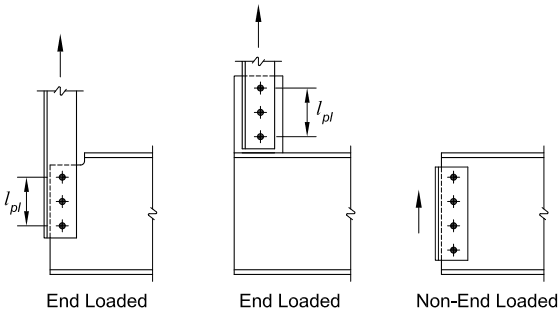
Figure description:
- Key Entities: Bolted structural connections, load arrows, and dimension labels.
- Connection Types:
- End Loaded: Two configurations where the applied load is at the end of the connected member.
- Non-End Loaded: One configuration where the load is applied along the member away from the connection end.
- Dimension Variable: represents the length of the bolt pattern in the direction of the load for end-loaded connections.
- Components:
- Structural Members: I-beams or channels.
- Fasteners: Linear patterns of three or four bolts per connection.
- Arrows: Indicate the direction of the applied tensile or shear force.
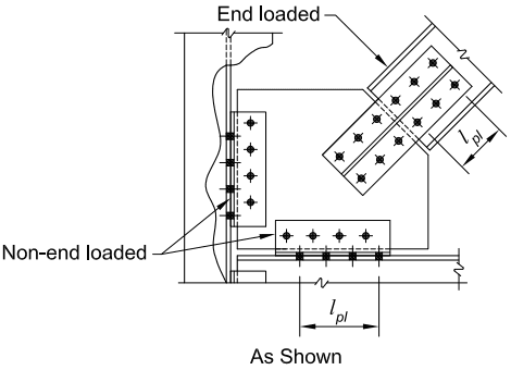
Figure description:
Key Entities and Information:
- End-loaded Connection: A diagonal structural member where the load is applied parallel to the fastener pattern length.
- Non-end-loaded Connections: Vertical and horizontal connection plates where the load is transverse to the fastener pattern.
- : Dimension indicating the fastener pattern length for both connection types.
- Components: Includes a central gusset plate connecting a vertical column, a horizontal beam, and a diagonal brace.
Fig. C-J3.1. End-loaded and non-end-loaded connection examples; pattern length.
J3.8 Combined Tension and Shear in Bearing-Type Connections
Tests have shown that the strength of bearing fasteners subjected to combined shear and tension resulting from externally applied forces can be closely defined by an ellipse (Kulak et al., 1987). The relationship is expressed as follows:
For design according to Section B3.1 (LRFD)
(C-J3-4a)
For design according to Section B3.2 (ASD)
(C-J3-4b)
where
nominal tensile stress, ksi (MPa)
- nominal shear stress, ksi (MPa)
- = required tensile stress, ksi (MPa)
- = required shear stress, ksi (MPa)
The elliptical relationship can be replaced, with only minor deviations, by three straight lines as shown in Figure C-J3.2. The sloped portion of the straight-line representation follows.
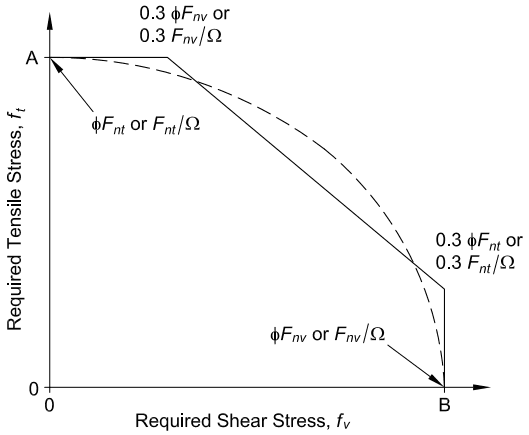
Figure description:
Tension-Shear Interaction Curves
Required Tensile Stress ( vs. Required Shear Stress (
Legend
- Linear approximation interaction curve — color: black; symbol: Solid line
- Elliptical interaction curve — color: black; symbol: Dashed line
Annotations
- A (text_label - position: y-axis intercept at (0, A))
- B (text_label - position: x-axis intercept at (B, 0))
- or (text_label - position: Value of A on the vertical axis)
- or (text_label - position: Value of B on the horizontal axis)
- 0.3 or 0.3 (text_label - position: x-coordinate where the upper horizontal segment of the solid line ends)
- 0.3 or 0.3 (text_label - position: y-coordinate where the right vertical segment of the solid line begins)
| Required Shear Stress, | Required Tensile Stress, (Solid Line) | Required Tensile Stress, (Dashed Line) |
|---|---|---|
| 0 | or | or |
| or | or | Elliptical curve point |
| or | or | 0 |
| or | 0 | 0 |
Notes: The chart represents structural design interaction curves for fasteners under combined tension and shear. 'A' represents the available tensile strength and 'B' represents the available shear strength. The solid line follows a multi-part linear interaction: a horizontal plateau, a sloped middle section, and a vertical tail. The dashed line represents the theoretical circular/elliptical interaction arc.
Fig. C-J3.2. Straight-line representation of elliptical solution.
For design according to Section B3.1 (LRFD)
ft fv = 1.3 (C-J3-5a) F Far
For design according to Section B3.2 (ASD)
(C-J3-5b)
which results in Equations J3-3a and J3-3b (Carter et al., 1997).
This latter representation offers the advantage that no modification of either type of stress is required in the presence of fairly large magnitudes of the other type. Note that Equations J3-3a and J3-3b can be rewritten so as to find the nominal shear strength per unit area, , as a function of the required tensile stress, . These formulations are as follows:
For design according to Section B3.1 (LRFD)
(C-J3-6a)
For design according to Section B3.2 (ASD)
(C-J3-6b)
The linear relationship was adopted for use in Section J3.8; generally, use of the elliptical relationship shown in Figure C-J3.2 is acceptable. A similar formulation using the elliptical solution follows.
For design according to Section B3.1 (LRFD)
(C-J3-7a)
For design according to Section B3.2 (ASD)
(C-J3-7b)
J3.9 High-Strength Bolts in Slip-Critical Connections
The design provisions for slip-critical connections have remained substantially the same for many years. The original provisions, using standard holes with in. (2 mm) clearance, were based on a probability of slip at code loads when tightened by the calibrated wrench method. This was comparable to a design for slip at approximately 1.4 to 1.5 times code loads. Because slip resistance was considered to be a serviceability design issue, this was determined to be an adequate safety factor.
Per the RCSC Guide to the Design Criteria for Bolted and Riveted Joints (Kulak et al., 1987), the provisions were revised to include oversized and slotted holes (Allan and Fisher, 1968). The revised provisions included a reduction in the allowable strength of 15% for oversized holes, 30% for long slots perpendicular, and 40% for long slots parallel to the direction of the load.
Except for minor changes and adding provisions for LRFD, the design of slip-critical connections was unchanged until the 2005 AISC Specification (AISC, 2005b) added a higher reliability level for slip-critical connections designed for use where selected by the engineer of record. The reason for this added provision was twofold. First, the use of slip-critical connections with oversize holes had become very popular because of the economy they afforded, especially with large bolted trusses and heavy vertical bracing systems. While the Commentary to the 2014 RCSC Specification (RCSC, 2014) indicated that only the engineer of record can determine if potential slippage at service loads could reduce the ability of the frame to resist factored loads, it did not give any guidance on how to do this. The 2005 AISC Specification provided a procedure to design to resist slip at factored loads if slip at service loads could reduce the ability of the structure to support factored loads.
Second, many of these connection details require large filler plates. There was a question about the need to develop these fills and how to do it. The 1999 LRFD Specification (AISC, 2000b) stated that as an alternative to developing the filler “the joint shall be designed as slip critical.” The RCSC Specification at this time stated, “The joint shall be designed as a slip-critical joint. The slip resistance of the joint shall not be reduced for the presence of fillers or shims.” Both Specifications required the joint to be checked as a bearing connection, which normally would require development of large fillers.
The answer to both of these issues was to provide a method for designing a connection with oversized holes to resist slip at the strength level and not require the bearing strength check for the connection. In order to do this, it was necessary to first determine as closely as possible what the slip resistance currently was for oversized holes. Then it was necessary to establish what would be an adequate level of slip resistance to be able to say the connection could resist slip at factored loads.
Three major research projects formed the primary sources for the development of the 2010 AISC Specification (AISC, 2010) provisions for slip-critical connections:
- (1) Dusicka and Lewis (2012) evaluated slip-critical connections with fills for the Research Council on Structural Connections. The work provides results relevant to all slip-critical connections with fills.
- (2) Grondin et al. (2007) is a two-part study that assembles slip resistance data from all known sources and analyzes reliability of slip-critical connections indicated by that data. A structural system configuration—a long-span roof truss—is evaluated to see if slip required more reliability in slip-critical connections.
- (3) Borello et al. (2009) conducted 16 large-scale tests of slip-critical connections in both standard and oversized holes, with and without thick fillers.
Deliberations considered in development of the 2010 AISC Specification slip-critical provisions include the following:
Slip Coefficient for Class A Surfaces. Grondin et al. (2007) rigorously evaluated the procedures for past tests on clean mill scale and eliminated a substantial number of them that did not meet the required protocol. The result was a recommended slip coefficient for Class A unpainted clean mill scale surfaces between 0.31 and 0.32.
Research on galvanized surfaces by Donahue et al. (2014) demonstrated that the practice of hand roughening as-galvanized faying surfaces through wire-brushing results in no significant improvement to the performance of galvanized slip-critical connections; therefore, the requirement to roughen as-galvanized surfaces has been eliminated. “As-galvanized” in this context means a hot-dipped galvanized surface with no supplemental treatment or coating applied to the zinc surface. Although this specification has deleted this requirement to hand roughen as-galvanized surfaces, it does not prohibit hand roughening because this has been a requirement for many decades with no known detrimental effects. Power wire brushing has been prohibited by this Specification and by the RCSC Specification and this prohibition still applies.
The previous requirement to hand-wire brush galvanized surfaces is believed to have been intended to remove wax or other coatings that may be applied to galvanized surfaces. It is believed that such coatings are not typically used when structural steel is hot-dip galvanized and therefore the justification for the previous requirement does not exist. Nonqualified coatings should not be applied to unpainted clean mill scale steel surfaces, blast-cleaned steel surfaces, qualified painted surfaces, or hot-dipped galvanized surfaces. If applied, nonqualified coatings must be removed.
Oversized Holes and Loss of Pretension. Borello et al. (2009) confirmed that there is no additional loss of pretension and that connections with oversized holes had similar slip resistance to the control group with standard holes.
Higher Pretension with Turn-of-Nut or Combined Method. The difficulty in knowing in advance what method of pretensioning would be used resulted in leaving the value of at 1.13 as established for the calibrated wrench method. The Specification does, however, allow the use of a higher value when approved by the engineer of record.
Shear/Bearing Strength. Borello et al. (2009) verified that connections with oversized holes, regardless of fill size, can develop the available bearing strength when the fill is developed. There was some variation in shear strength with filler size but the maximum reduction for thick fillers was approximately 15% when undeveloped.
Fillers in Slip-Critical Connections. Borello et al. (2009) indicated that filler thickness did not reduce the slip resistance of the connection. Borello et al. (2009) and Dusicka and Lewis (2012) indicated that multiple fillers, as shown in Figure C-J3.3, reduced the slip resistance. It was determined that a factor for the number of fillers should be included in the design equation. A plate welded to the connected member or connection plate is not a filler plate and does not require this reduction factor.
The 2010 AISC Specification provisions for slip-critical connections were based on the following conclusions:
- (a) The mean and coefficient of variation in Class A slip-critical connections supports the use of , not 0.33 or 0.35 . It was expected that the use of would achieve more consistent reliability while using the same resistance factors for both slip classes. The value of was selected and the resistance and safety factors reflect this value.
- (b) A factor, , to reflect the use of multiple filler plates was added to the equation for nominal slip resistance resulting in
(C-J3-8)
where
factor for fillers; coefficient to reflect the reduction in slip due to multiple fills
- (c) is defined as a parameter derived from statistical analysis to calculate nominal slip resistance from statistical means developed as a function of installation method and specified minimum pretension and the level of slip probability selected.
- (d) The surfaces of fills must be prepared to the same or higher slip coefficient as the other faying surfaces in the connection.
- (e) The reduction in design slip resistance for oversized and slotted holes is not due to a reduction in tested slip resistance but is a factor used to reflect the consequence of slip. It was continued at the 0.85 level but clearly documented as a factor increasing the slip resistance of the connection.
The Specification also recognizes a special type of slip-resistant connection for use in built-up compression members in Section E6 where pretensioned bolts with Class A or B faying surfaces are required for end connections, but the connection is designed using the bearing strength of the bolts. This is based on the need to prevent relative movement between elements of the compression member at the ends.
Reliability levels for slip resistance in oversized holes and slots parallel to the load given in Table C-J3.1 exceed reliability levels associated with the nominal strength of main members in the Specification when turn-of-nut pretensioning is used. Reliability of slip resistance when other tightening methods are used exceeds previous
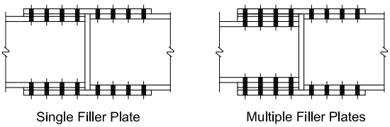
Figure description:
- Subject: Structural diagrams of bolted connections with filler plates.
- Left Diagram (Single Filler Plate: Shows a connection using one thick filler plate to bridge a gap between structural members.
- Right Diagram (Multiple Filler Plates: Shows a connection using a stack of thinner filler plates to bridge the same gap.
- Key Components:
- Structural main members (left and right sides.
- Vertical connection plates.
- Filler plates (single vs. stacked.
- Vertical lines representing bolt locations through the assembly.
Fig C-J3.3. Single and multiple filler plate configurations.
TABLE C-J3.1 Reliability Index, β, for Slip Resistance
| Turn-of-Nut or Combined Method | Other Methods (Calibrated Wrench, Twist-off Type, DTI) | ||||
|---|---|---|---|---|---|
| Group | Class | Standard Holes, Parallel Slots | Oversized Holes | Standard Holes, Parallel Slots | Oversized Holes |
| Group 120 (e.g., A325) | Class A (µ = 0.30) | 2.39 | 2.92 | 1.82 | 2.41 |
| Class B (µ = 0.50) | 2.78 | 3.52 | 2.17 | 2.83 | |
| Group 144 or 150 (e.g., A490, F3148) | Class A (µ = 0.30) | 2.01 | 2.63 | 1.53 | 2.13 |
| Class B (µ = 0.50) | 2.47 | 3.20 | 1.86 | 2.54 | |
levels and is sufficient to prevent slip at load levels where inelastic deformation of the connected parts is expected. Because the effect of slip in standard holes is less than that of slip in oversized holes, the reliability indices permitted for standard holes are lower than those for oversized holes. This increased data on the reliability of these connections allowed the return to a single design level of slip resistance similar to the 2014 RCSC Specification (RCSC, 2014) and previous AISC Specifications.
J3.11 Bearing and Tearout Strength at Bolt Holes
Provisions for bearing strength of bolts differ from those for bearing strength of pins as given in Section J7.
Bearing strength values are provided as a measure of the strength of the material upon which a bolt bears, not as a protection to the fastener, which needs no such protection. Accordingly, the same bearing value applies to all joints assembled by bolts, regardless of fastener shear strength or the presence or absence of threads in the bearing area.
Material bearing strength may be limited either by bearing deformation of the hole or by tearout (a bolt-by-bolt block shear rupture) of the material upon which the bolt bears. In earlier editions of the Specification, both limit states were defined by one equation and termed bearing limit states. For the 2016 edition, the limit states were separated to permit clear reference to each of the limits and their corresponding equations. Kim and Yura (1996) and Lewis and Zwerneman (1996) confirmed the bearing strength provisions for the bearing case wherein the nominal bearing strength, , is equal to and is equal to 2.4, 3.0, or 2.0 depending upon hole type and acceptability of hole ovalization at ultimate load, as indicated in Section J3.11. However, this same research indicated the need for different bearing strength provisions when tearout failure would control. Appropriate equations for tearout strength as a function
of clear distance, , are therefore provided and this formulation is consistent with that in the RCSC Specification (RCSC, 2020).
Frank and Yura (1981) demonstrated that hole elongation greater than in. ( 6 mm ) will generally begin to develop as the bearing force is increased beyond , especially if it is combined with high tensile stress on the net section, even though rupture does not occur. For a long-slotted hole with the slot perpendicular to the direction of force, the same is true for a bearing force greater than . For standard, oversized, and short-slotted holes, independent of load direction, or a longslotted hole with the slot parallel to the direction of force, an upper bound of is specified, which anticipates hole ovalization, defined as a deformation greater than in. ( 6 mm ) at maximum strength.
Additionally, to simplify and generalize tearout strength calculations, the provisions are based upon a clear-distance formulation. Provisions prior to 1999 utilized edge distances and bolt spacings measured to hole centerlines with adjustment factors to account for varying hole type and orientation, as well as minimum edge distance requirements. The effective strength of an individual fastener is the lesser of the fastener shear strength per Section J3.7 and the bearing and tearout strength at the bolt hole per Section J3.11. The strength of a bolt group is a function of strain compatibility and is dependent on the relative stiffnesses of the bolts and connected parts. For typical connections, such as those shown in the AISC Steel Construction Manual (AISC, 2017), it is acceptable to calculate the shear, bearing, and tearout limit states for each bolt in the same connected part and sum the lowest value of the bolt shear or the controlling bearing or tearout limit for each bolt to determine the group strength. The intent is that the separate bearing and tearout equations in this Specification be treated in the same way as the combined equations in the 2010 AISC Specification. This ignores the potential for interaction of these limit states in multiple connected parts, but that impact is small enough in common connection details within the range of the connections shown in Part 10 of the AISC Steel Construction Manual (AISC, 2017), to allow the benefit of this practical simplification in design. Nonstandard connections may be more sensitive to this interaction; in that case, a more exact approach may be necessary.
A new limit state, tearout, for connections made using bolts or rods that pass completely through an unstiffened box member or HSS, has been added. It adopts the same nominal strengths used for bolts in standard holes. Though through-bolts do not provide confinement to the joined plies, the shear rupture check for pin-connected members in Section D5.1 predicts greater strength for pins, which also do not provide confinement, than for bolts. Therefore, the more conservative provision has been adopted.
J3.13 Wall Strength at Tension Fasteners
With any connection configuration where the fasteners transmit a tensile force to the HSS or box-section wall, a rational analysis must be used to determine the appropriate limit states. These may include a yield-line mechanism in the wall or pull-out through the wall, in addition to applicable limit states for the fasteners subjected to tension.