C-J10J10 Flanges and webs with concentrated forces
PDF page 579 · AISC 360-22
The Specification separates flange and web strength requirements into distinct categories representing different limit states: flange local bending (Section J10.1), web local yielding (Section J10.2), web local crippling (Section J10.3), web sidesway buckling (Section J10.4), web compression buckling (Section J10.5), and web panelzone shear (Section J10.6). These limit state provisions are applied to two distinct types of concentrated forces normal to member flanges:
- (a) Single concentrated forces that may be tensile (such as those delivered by ten- sion hangers) or compressive (such as those delivered by bearing plates at beam interior positions, reactions at beam ends, and other bearing connections)
- (b) Double concentrated forces, one tensile and one compressive, that form a couple on the same side of the loaded member, such as that delivered to column flanges through welded and bolted moment connections
Flange local bending applies only for tensile forces, web local yielding applies to both tensile and compressive forces, and the remainder of these limit states apply only to compressive forces.
Transverse stiffeners, also called continuity plates, and web doubler plates are only required when the concentrated force exceeds the available strength given for the applicable limit state. It is often more economical to choose a heavier member than to provide such reinforcement (Carter, 1999; Troup, 1999). The demand may be determined as the largest flange force from the various load cases, although the demand may also be taken as the gross area of the attachment delivering the force multiplied by the specified minimum yield strength, . Stiffeners and doublers, and their attaching welds, are sized for the difference between the demand and the applicable limit state strength. Detailing and other requirements for stiffeners are provided in Sections J10.7 and J10.8; requirements for doublers are provided in Section J10.9.
The provisions in Section J10 have been developed for use with wide-flange sections and similar built-up shapes; with some judgment, they can also be applied to other shapes. The Commentary related to the individual subsections provides further detail relative to testing and assumptions. Some guidance relating the application of these checks to other sections is provided here. When applied to members with multiple webs, such as rectangular hollow structural sections (HSS) and box sections, the strength calculated in this section should be multiplied by the number of webs.
Flange local bending assumes a single concentrated line load applied transverse to the beam web. It is not generally applicable to other shapes or other loading conditions. For instance, point loads, such as those delivered through bolts in tension, are typically addressed using yield-line methods (Dowswell, 2013b). The web local yielding provisions assume that concentrated loads are distributed into the member spread out with a slope of 2.5:1. This model is likely appropriate for conditions beyond rolled wide flanges. For example, it could be used to determine the local yielding strength for C-shapes where the concentrated load is delivered opposite the web. It has also been applied to HSS where is typically taken as the outside corner radius. If the radius is not known, it can be assumed to be , as implied in Section B4.1b(d). If a fillet weld is present at the juncture of the web and the flange, additional distribution of stress through this weld is often assumed. Web local crippling has been applied to HSS members assuming and are both equal to the design wall thickness and the depth, , is equal to the flat dimension of the HSS sidewall. When the radius is not known, it is typically assumed to be , leading to a depth of . For box sections, and can be taken as the clear distance between the flanges. Equations J10-4, J10-5a, and J10-5b assume restraint between the flange and the web, which may not be present when small and/or intermittent welds join the elements of built-up sections. Web sidesway buckling is not generally a consideration for typical closed sections like HSS members. Web compression buckling has been applied to HSS members assuming and are both equal to the design wall thickness and the depth, , is equal to the flat dimension of the HSS sidewall. For box sections, can be taken as the clear distance between the flanges. Equation J10-8 assumes pinned restraints at the ends of the web. The web panel-zone shear equations are applicable to rolled wide-flange sections and similar built-up shapes. The equations in Section J10.6 neglect web stability. For deep members with thin webs, stability should not be neglected. See Chapter G and AISC Design Guide 16, Flush and Extended Multiple-Row Moment End-Plate Connections (Murray and Shoemaker, 2002). Additional inelastic shear strength due to flange deformation is recognized in Equations J10-11 and J10-12, which should not be applied to sections other than rolled wide-flange sections and similar built-up shapes. Though the Specification only provides explicit equations for rolled wide-flange sections, panelzone shear is a consideration for other member types, such as HSS and box sections where moment is transferred at a panel zone.
J10.1 Flange Local Bending
Where a tensile force is applied through a plate welded across a flange, that flange must be sufficiently rigid to prevent deformation of the flange and the corresponding high stress concentration in the weld in line with the web.
The effective column flange length for local flange bending is (Graham et al., 1960). Thus, it is assumed that yield lines form in the flange at in each direction from the point of the applied concentrated force. To develop the fixed edge consistent with the assumptions of this model, an additional , and therefore a total of , is required for the full flange-bending strength given by Equation J10-1. In the absence of applicable research, a reduction has been introduced for cases wherein the applied concentrated force is less than from the member end.
The strength given by Equation J10-1 was originally developed for moment connections but also applies to single concentrated forces, such as tension hangers consisting of a plate welded to the bottom flange of a beam and transverse to the beam web. In the original tests, the strength given by Equation J10-1 was intended to provide a lower bound to the force required for weld fracture, which was aggravated by the uneven stress and strain demand on the weld caused by the flange deformation (Graham et al., 1959).
Recent tests on welds with minimum Charpy V-notch (CVN) toughness requirements show that weld fracture is no longer the failure mode when the strength given by Equation J10-1 is exceeded. Rather, it was found that the strength given by Equation J10-1 is consistently less than the force required to separate the flanges in typical column sections by in. ( 6 mm ) (Hajjar et al., 2003; Prochnow et al., 2000). This amount of flange deformation is on the order of the tolerances in ASTM A6/A6M, and it is believed that if the flange deformation exceeded this level it could be detrimental to other aspects of the performance of the member, such as flange local buckling. Although this deformation could also occur under compressive normal forces, it is customary that flange local bending is checked only for tensile forces (because the original concern was weld fracture). Therefore, it is not required to check flange local bending for compressive forces.
The provision in Section J10.1 is not applicable to moment end-plate and tee-stub type connections. For these connections, see AISC Design Guide 13, Stiffening of Wide-Flange Columns at Moment Connections: Wind and Seismic Applications (Carter, 1999) or the AISC Steel Construction Manual (AISC, 2017).
J10.2 Web Local Yielding
The web local yielding provisions, Equations J10-2 and J10-3, apply to both compressive and tensile forces of bearing and moment connections. These provisions are intended to limit the extent of yielding in the web of a member into which a force is being transmitted. The provisions are based on tests on two-sided directly welded girder-to-column connections (cruciform tests) (Sherbourne and Jensen, 1957) and were derived by considering a stress zone that spreads out with a slope of 2:1. Graham et al. (1960) report pull-plate tests and suggest that a 2.5:1 stress gradient is more appropriate. Recent tests confirm that the provisions given by Equations J10-2 and J10-3 are slightly conservative and that the yielding is confined to a length consistent with the slope of 2.5:1 (Hajjar et al., 2003; Prochnow et al., 2000).
J10.3 Web Local Crippling
The web local crippling provisions, Equations J10-4 and J10-5, apply only to compressive forces. Originally, the term “web crippling” was used to characterize a phenomenon now called web local yielding, which was then thought to also predict web crippling adequately. The first edition of the AISC LRFD Specification (AISC, 1986) was the first AISC Specification to distinguish between web local yielding and web local crippling. Web local crippling was defined as crumpling of the web into buckled waves directly beneath the load, occurring in more slender webs, whereas web local yielding is yielding of that same area, occurring in stockier webs.
Equations J10-4 and J10-5 are based on research reported in Roberts (1981). The increase in Equation J10-5b for was developed after additional testing to better represent the effect of longer bearing lengths at ends of members (Elgaaly and Salkar, 1991). All tests were conducted on bare steel beams without the expected beneficial contributions of any connection or floor attachments. Thus, the resulting provisions are considered conservative for such applications. Kaczinski et al. (1994) reported tests on cellular box beams with slender webs and confirmed that these provisions are appropriate in this type of member as well.
The equations were developed for bearing connections but are also generally applicable to moment connections. Equation J10-5a and J10-5b are intended to be applied to beam ends where the web of the beam end is not supported, for example, at the end of a seated connection. Where beam end connections are accomplished with the use of web connections, Equation J10-4 should be used to calculate the available strength for the limit state of web local crippling. Figure C-J10.1 illustrates examples of appropriate applications of Equations J10-4 and J10-5 when checking web local crippling for various framing conditions.
The web local crippling phenomenon has been observed to occur in the web adjacent to the loaded flange. For this reason, a stiffener (or stiffeners) or a doubler plate extending at least three-quarters of the web depth is needed to eliminate this limit state. The stiffener depth was changed in the 2016 AISC Specification in response to research by Salker et al. (2015).
J10.4 Web Sidesway Buckling
The web sidesway buckling provisions, Equations J10-6 and J10-7, apply only to compressive forces in bearing connections and do not apply to moment connections. The web sidesway buckling provisions were developed after observing several unexpected failures in tested beams (Summers and Yura, 1982; Elgaaly, 1983). In those tests, the compression flanges were braced at the concentrated load, the web was subjected to compression from a concentrated load applied to the flange, and the tension flange buckled as shown in Figure C-J10.2.
Web sidesway buckling will not occur in the following cases:
(a) For flanges restrained against rotation (such as when connected to a slab), when
(C-J10-1)
(b) For flanges not restrained against rotation, when
ht
1.7 (C-J10-2) Ls/by
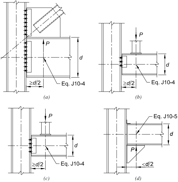
Figure description:
Key Information: Web Local Crippling Equation Applications
The image illustrates four scenarios (a, b, c, and d for applying web local crippling equations in structural steel connections:
- Entities:
- P: Concentrated load applied to the beam.
- d: Depth of the beam section.
- Distance: Measured from the member end to the point of load application.
- Application Criteria:
- Eq. J10-4: Applied when the concentrated load is located at a distance from the member end (shown in diagrams a, b, and c.
- Eq. J10-5: Applied when the concentrated load is located at a distance from the member end (shown in diagram d.
- Connection Types:
- (a: Gusset plate connection with a diagonal brace.
- (b & (c: Concentrated load applied via a transverse member on the top flange.
- (d: Concentrated load applied via a seat connection/bracket on the bottom flange near the end of the beam.
Fig. C-J10.1. Examples of application of the web local crippling equations.
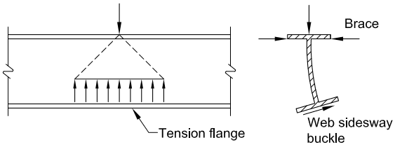
Figure description:
The image consists of two technical diagrams illustrating structural mechanics in steel beams:
- Left Diagram (Web Force Distribution: Depicts a concentrated vertical load applied to the top flange of a beam. Dashed lines illustrate the triangular distribution of force through the web toward the bottom Tension flange.
- Right Diagram (Web Sidesway Buckling: Shows an I-beam cross-section undergoing Web sidesway buckle. Key elements include:
- A vertical load on the top flange.
- A Brace providing lateral restraint to the top flange.
- Lateral displacement (buckling of the web and rotation/movement of the bottom flange.
Fig. C-J10.2. Web sidesway buckling.
Specification for Structural Steel Buildings, August 1, 2022 AMERICAN INSTITUTE OF STEEL CONSTRUCTION
Web sidesway buckling can be prevented by the proper design of lateral bracing or stiffeners at the load point. It is suggested that local bracing at both flanges be designed for 1% of the concentrated force applied at that point. If stiffeners are used, they must extend from the load point through at least one-half the beam or girder depth. In addition, the pair of stiffeners must be designed to carry the full load. If flange rotation is permitted at the loaded flange, neither stiffeners nor doubler plates are effective.
Equations J10-6 and J10-7 address doubly symmetric sections, consistent with the description in the introduction to Section J10, “wide-flange sections and similar built-up shapes.” Summers and Yura (1982) suggest, “For singly symmetric cross sections in the plane of bending, should be taken as twice the depth of web in compression.”
J10.5 Web Compression Buckling
The web compression buckling provision, Equation J10-8, applies only when there are compressive forces on both flanges of a member at the same cross section, such as might occur at the bottom flange of two back-to-back moment connections under gravity loads. Under these conditions, the slenderness of the member web must be limited to avoid the possibility of buckling. Equation J10-8 is applicable to a pair of moment connections and to other pairs of compressive forces applied at both flanges of a member, for which is approximately less than 1, where is the length of bearing and is the depth of the member. Figure C-J10.3 illustrates examples of some appropriate and not appropriate applications of Equation J10-8 when checking web compression buckling. When is not small, the member web should be designed as a compression member in accordance with Chapter E. Equation J10-8 is based on the equation for the elastic buckling strength of a simply supported plate subjected to equal and opposite concentrated forces. The coefficient, 24, has been adjusted downward to reflect the lower bound of test results (Newlin and Chen, 1971).
Where the flanges are not restrained against translation [for example, see Figure C-J10.3(c)], Section J10.5 is not applicable. In such cases, the buckling mode interaction between the member delivering the force and the supporting member needs to be considered by the engineer of record. Refer to Chapter C and Appendix 6 for additional information.
Equation J10-8 is predicated on an interior member loading condition. In the absence of applicable research, a 50% reduction has been introduced for cases wherein the compressive forces are close to the member end.
J10.6 Web Panel-Zone Shear
This section addresses panel-zone behavior of wide-flange sections and similar built-up shapes. Panel-zone shear can also occur in other members, such as HSS and box sections and deep and tapered built-up shapes. For these general conditions, the shear strength should be determined in accordance with Chapter G.
Column web shear stresses may be significant within the boundaries of the rigid connection of two or more members with their webs in a common plane. Such webs must be reinforced when the required force, ΣRu for LRFD or ΣRa for ASD, along plane A-A in Figure C-J10.4 exceeds the column web available strength, fRn or Rn Ω, respectively.
For design according to Section B3.1 (LRFD)
(C-J10-3a)
where
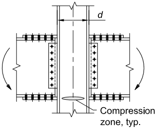
Figure description:
Structural Beam-to-Column Moment Connection Diagram
- Key Entities:
- Column: Central vertical member with width dimension .
- Beams: Horizontal members attached to both sides of the column.
- Connection Hardware: Bolted flange plates and web shear tabs.
- Key Details:
- Applied Moments: Curved arrows indicating moment forces acting on the connection.
- Compression zone, typ.: Labeled elliptical region at the bottom of the joint, identifying where compressive forces are concentrated.
- Dimension : Specifies the depth/width of the column section.
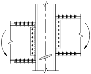
Figure description:
This structural diagram depicts a beam-to-column moment connection:
- Main Entities: A central vertical column joined with two horizontal beams.
- Connection Details: Bolted flange plates (top and bottom and bolted vertical web plates (shear tabs connect the beams to the column flanges.
- Applied Forces: Curved arrows indicate opposing rotational moments on the left and right beams.
- Internal Stress: A shaded diagonal oval within the column's panel zone represents shear deformation or potential failure resulting from the applied moments.
- (a) Two back-to-back moment connections under gravity load, Section J10.5 applies
- (b) Offset back-to-back moment connections under gravity load, Section J10.5 applies
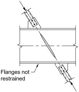
Figure description:
Structural Engineering Diagram: Local Web Buckling
- Components: Horizontal beam with top and bottom flanges, two diagonal bracing members attached via gusset plates.
- Forces: Compressive loads (indicated by arrows acting along a diagonal path through the beam's web.
- Failure Mode: A shaded elliptical region in the center of the web illustrates localized yielding or buckling aligned with the bracing force.
- Condition Note: "Flanges not restrained" points to the lower flange, indicating a lack of lateral support at that connection point.
- (c) Vertical bracing intersecting a floor beam with flanges not restrained, Section J10.5 does not apply
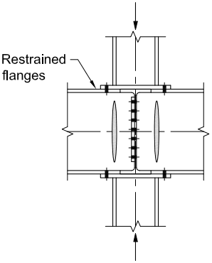
Figure description:
-
Type: Structural engineering diagram of a beam-to-column connection.
-
Key Entities:
- Vertical Column: Shown with axial load arrows at the top and bottom.
- Horizontal Beams: Intersect the column from the left and right sides.
- Restrained Flanges: Labeled connection points where beam flanges are secured to the column.
- Fasteners: Black marks indicating bolts or welds at the flange and web interfaces.
- Continuity Plates: Horizontal plates within the column aligned with the beam flanges.
- Beam Web Details: Elliptical shapes illustrated on the beam webs near the joint.
-
(d) Columns bearing above and below a beam with restrained flanges, Section J10.5 applies
Fig. C-J10.3. Examples of some appropriate and not appropriate applications of web compression buckling.
Mu2 =Mu2L-Mu2G
= difference between the moments due to the factored lateral loads, , and the moments due to factored gravity loads, , on the leeward side of the connection, kip-in. (N-mm)
distance between flange forces in the moment connection, in. (mm)
For design according to Section B3.2 (ASD)
(C-J10-3b)
where
- = sum of the moments due to the nominal lateral loads, , and the mo ments due to nominal gravity loads, , on the windward side of the connection, kip-in. (N-mm)
- = difference between the moments due to the nominal lateral loads, , and the moments due to nominal gravity loads, , on the leeward side of the connection, kip-in. (N-mm)
Historically (and conservatively), 0.95 times the beam depth has been used for .
If, for LRFD, , or for ASD, , no reinforcement is necessary; in other words, , where is the column web thickness.
Equations J10-9 and J10-10 limit panel-zone behavior to the elastic range. While such connection panels possess large reserve capacity beyond initial general shear yielding, the corresponding inelastic joint deformations may adversely affect the strength and stability of the frame or story (Fielding and Huang, 1971; Fielding and Chen, 1973). Panel-zone shear yielding affects the overall frame stiffness and, therefore, the resulting second-order effects may be significant. The shear and axial load interaction expression of Equation J10-10, as shown in Figure C-J10.5, provides elastic panel behavior.
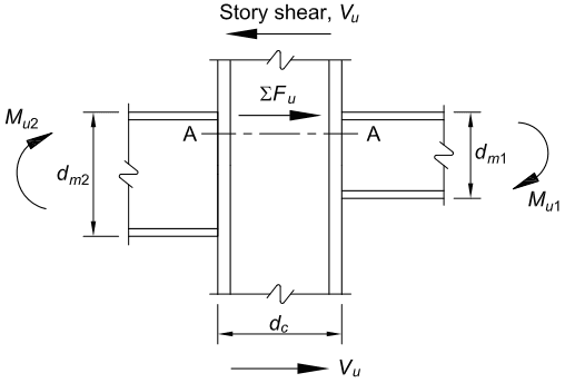
Figure description:
Key Information:
- Subject: Diagram of LRFD forces in a structural steel panel zone (beam-to-column connection.
- Entities:
- Column: Vertical member with depth .
- Beams: Horizontal members framing into the column with depths (right and (left.
- Panel Zone: The rectangular region of the column web bounded by the beam flanges.
- Forces and Moments:
- : Story shear acting at the top and bottom of the connection.
- : Moments applied by the beams on the right and left sides, respectively.
- : Resultant horizontal force acting within the panel zone across section A-A.
- Section A-A: Horizontal plane through the panel zone used for equilibrium analysis.
Fig. C-J10.4. LRFD forces in panel zone (ASD forces are similar).
If adequate connection ductility is provided and the frame analysis considers the inelastic panel-zone deformations, the additional inelastic shear strength is recognized in Equations J10-11 and J10-12 by the factor
This increase in shear strength due to inelasticity has been most often utilized for the design of frames in high-seismic applications and should be used when the panel zone is designed to develop the strength of the members from which it is formed.
The shear and axial interaction expression incorporated in Equation J10-12, as shown in Figure C-J10.6, recognizes that when the panel-zone web has completely yielded in shear, the axial column load is resisted by the flanges.
J10.7 Unframed Ends of Beams and Girders
Full-depth stiffeners are required at unframed ends of beams and girders not otherwise restrained to avoid twisting about their longitudinal axes. These stiffeners are full depth but not fitted. They connect to the restrained flange but do not need to continue beyond the toe of the fillet at the far flange unless connection to the far flange is necessary for other purposes, such as resisting compression from a concentrated load on the far flange.
J10.8 Additional Stiffener Requirements for Concentrated Forces
For guidelines on column stiffener design, see Carter (1999), Troup (1999), and Murray and Sumner (2004).
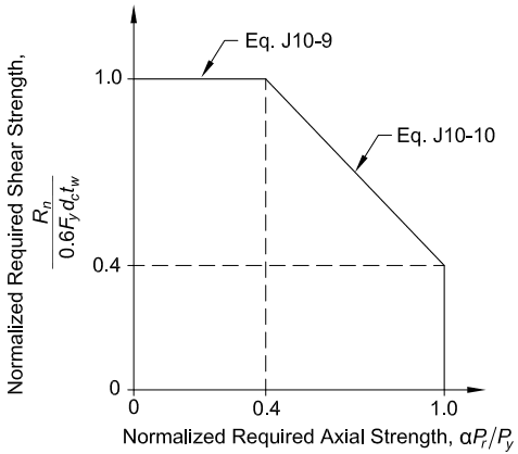
Figure description:
Interaction of Shear and Axial Forces
Normalized Required Shear Strength vs. Normalized Required Axial Strength
Annotations
- Eq. J10-9 (text_label - position: Applies to the segment where Normalized Required Axial Strength is less than or equal to 0.4 and Normalized Required Shear Strength is 1.0)
- Eq. J10-10 (text_label - position: Applies to the sloped segment between (0.4, 1.0 and (1.0, 0.4)))
- x = 0.4 (vertical_line - position: x = 0.4)
- y = 0.4 (horizontal_line - position: y = 0.4)
| Normalized Required Axial Strength, | Normalized Required Shear Strength, ) |
|---|---|
| 0.0 | 1.0 |
| 0.4 | 1.0 |
| 1.0 | 0.4 |
Notes: The graph shows a piecewise linear relationship for normalized required shear strength as a function of normalized required axial strength. The relationship is constant at 1.0 until a normalized axial strength of 0.4, after which it decreases linearly to 0.4 when normalized axial strength is 1.0.
Fig. C-J10.5. Interaction of shear and axial force—elastic.
For rotary-straightened W-shapes, an area of reduced notch toughness is sometimes found in a limited region of the web immediately adjacent to the flange, referred to as the “k-area,” as illustrated in Figure C-J10.7 (Kaufmann et al., 2001). The k-area is defined as the region of the web that extends from the tangent point of the web and the flange-web fillet (AISC k-dimension) a distance 12 in. (38 mm) into the web beyond the k-dimension. Following the 1994 Northridge earthquake, there was a ten- dency to specify thicker transverse stiffeners that were groove-welded to the web and flange, and thicker doubler plates that were often groove-welded in the gap between the doubler plate and the flanges. These welds were highly restrained and may have caused cracking during fabrication in some cases (Tide, 2000). AISC (1997b) recom- mended that the welds for continuity plates terminate away from the k-area.
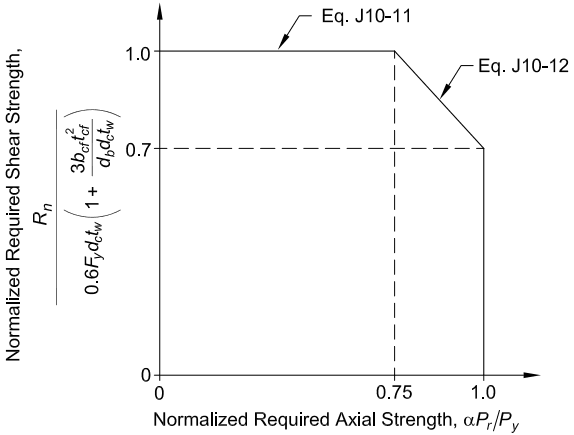
Figure description:
Interaction of Normalized Shear and Axial Strengths Diagram
Normalized Required Shear Strength vs. Normalized Required Axial Strength
Annotations
- Eq. J10-11 (text_label - position: Horizontal line segment at y = 1.0, from x = 0 to x = 0.75)
- Eq. J10-12 (text_label - position: Sloped line segment from (x=0.75, y=1.0 to (x=1.0, y=0.7)))
- y = 0.7 (horizontal_line - position: y = 0.7)
- x = 0.75 (vertical_line - position: x = 0.75)
| Normalized Required Axial Strength (alpha*Pr/Py) | Normalized Required Shear Strength | Equation Reference |
|---|---|---|
| 0.00 | 1.0 | Eq. J10-11 |
| 0.75 | 1.0 | Eq. J10-11 |
| 0.75 | 1.0 | Eq. J10-12 |
| 1.00 | 0.7 | Eq. J10-12 |
Notes: The Y-axis represents Normalized Required Shear Strength, defined as: Rn / [0.6 * Fy * dc * tw * (1 + (3 * bcf * tcf^2 / (db * dc * tw. The X-axis represents Normalized Required Axial Strength, defined as alpha * Pr / Py. The chart illustrates the interaction boundary governed by Equations J10-11 and J10-12.)))
Fig. C-J10.6. Interaction of shear and axial force—inelastic.
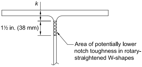
Figure description:
Entity: Representative "k-area" of a wide-flange (W-shape steel member.
Key Details:
- k dimension: Extends from the outer face of the flange to the toe of the web-to-flange fillet.
- Highlighted Zone: A cross-hatched area on the web extending 1½ in. (38 mm below the k dimension.
- Technical Note: This specific region is identified as an area of potentially lower notch toughness in rotary-straightened W-shapes.
Fig. C-J10.7. Representative "k-area" of a wide-flange shape.
Pull-plate tests (Dexter and Melendrez, 2000; Prochnow et al., 2000; Hajjar et al., 2003) and full-scale beam-column joint testing (Bjorhovde et al., 1999; Dexter et al., 2001; Lee et al., 2002a) have shown that this problem can be avoided if the column stiffeners are fillet welded to both the web and the flange, the corner is clipped at least in. (38 mm), and the fillet welds are stopped short by a weld leg length from the edges of the cutout, as shown in Figure C-J10.8. These tests also show that groove welding the stiffeners to the flanges or the web is unnecessary, and that the fillet welds performed well with no problems. If there is concern regarding the development of the stiffeners using fillet welds, the corner clip can be made so that the dimension along the flange is in. (19 mm) and the dimension along the web is in. (38 mm).
Tests have also shown the viability of fillet welding doubler plates to the flanges, as shown in Figure C-J10.9 (Prochnow et al., 2000; Dexter et al., 2001; Lee et al., 2002a; Hajjar et al., 2003). It was found that it is not necessary to groove weld the doubler plates and that they do not need to be in contact with the column web to be fully effective.
J10.9 Additional Doubler Plate Requirements for Concentrated Forces
When required, doubler plates are to be designed using the appropriate limit state requirements for the type of loading. The sum of the strengths of the member element and the doubler plate(s) must exceed the required strength, and the doubler plate must be welded to the member element.
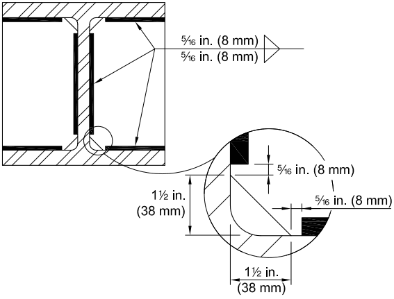
Figure description:
- Entity: Steel I-beam/member section with stiffener plates.
- Key Feature: Recommended placement of stiffener fillet welds to avoid the "k-area" (the radius between the flange and web.
- Weld Specification: 5/16 in. (8 mm fillet welds indicated by weld symbols on both sides of the plate.
- Clearance Dimensions:
- Weld termination is setback 5/16 in. (8 mm from the edge of the stiffener corner clip.
- Stiffener corner clip/cope dimension: 1 1/2 in. (38 mm vertically and horizontally to clear the web-to-flange fillet.
Fig. C-J10.8. Recommended placement of stiffener fillet welds to avoid contact with "k-area."
J10.10 Transverse Forces on Plate Elements
Designing connections to resist forces transverse to the plane of plate elements as shown in Figure C-J10.10 is often not the best solution but where it is required, there must be sufficient flexure and shear strength. This section addresses only strength. Stiffness may also be a consideration; in particular, for moment connections, Section B3.4b must be satisfied. Simple beam connections are required to provide for rotational ductility and usually do not need to have transverse plate elements designed for flexure.
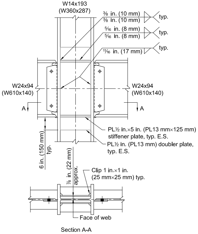
Figure description:
Key Entities and Information:
- Main Structural Members:
- Vertical Column: W14x193 (W360x287
- Horizontal Beams: W24x94 (W610x140 on both sides.
- Stiffening Components:
- Stiffener Plate: PL 1/2 in. x 5 in. (PL13 mm x 125 mm, typical both sides (E.S..
- Doubler Plate: PL 1/2 in. (PL13 mm, typical both sides (E.S., extending 6 in. (150 mm beyond beam flanges.
- Weld Details:
- Stiffener to Column Flange: 3/8 in. (10 mm fillet welds.
- Stiffener to Doubler Plate/Web: 5/16 in. (8 mm fillet welds.
- Doubler Plate to Column Flange: 11/16 in. (17 mm fillet welds.
- Section A-A Details:
- Face of Web Gap: 7/8 in. (22 mm approx. between doubler plates.
- Corner Clips: 1 in. x 1 in. (25 mm x 25 mm typical on stiffener plates.
- Beam Connection: Bolted shear tabs connecting beam webs to the column.
Fig. C-J10.9. Example of fillet welded doubler plate and stiffener details.
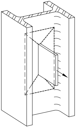
Figure description:
- Subject: Structural diagram showing yield lines on a beam web.
- Key Entities:
- I-Beam/Wide Flange: The primary structural member.
- Transverse Plate: A plate attached perpendicularly to the beam's web.
- Force Vector: An arrow indicating a transverse pulling force acting on the plate.
- Yield Lines: Dashed lines illustrating the plastic deformation pattern on the web due to the applied force.
- Action: The transverse force on the plate causes a specific yield line mechanism in the supporting plate element (beam web.
Fig. C-J10.10. Yield lines due to transverse forces on plate elements.