C-J4J4 Affected elements of members and connecting elements
PDF page 574 · AISC 360-22
- Strength of Elements in Tension
Both experimental and theoretical analyses have shown that the area effective in resisting tensile loads can be limited by the ability of the stresses to disperse through the element. The dispersion angle is dependent on the element geometry, the level of constraint, and the inelastic deformation capacity (Dowswell, 2013b). Due to the large inelastic deformation capacity of gusset plates and similar elements subjected to tensile loads, the effective width can be calculated with a 45° dispersion angle.
- Strength of Elements in Shear
Prior to the 2005 AISC Specification, the resistance factor for shear yielding had been 0.90, which was equivalent to a safety factor of 1.67. In the 1989 ASD Specification (AISC, 1989), the allowable shear yielding stress was , which was equivalent to a safety factor of 1.5. To make the LRFD approach in the 2005 AISC Specification consistent with prior editions of the ASD Specification, the resistance and safety factors for shear yielding became 1.00 and 1.50, respectively. The resulting increase in LRFD design strength of approximately is justified by the long history of satisfactory performance of ASD use.
- Block Shear Strength
Tests on coped beams indicated that a tearing failure mode (rupture) can occur along the perimeter of the bolt holes as shown in Figure C-J4.1 (Birkemoe and Gilmor, 1978). This block shear mode combines tensile failure on one plane and shear failure on a perpendicular plane. The failure path is defined by the centerlines of the bolt holes. This same condition exists on welded connections at beam copes. The tensile plane is the length of the horizontal portion of the weld and the shear plane runs from the horizontal weld to the bottom of the cope.
The block shear failure mode is not limited to coped ends of beams; other examples are shown in Figures C-J4.1 and C-J4.2. The block shear failure mode must also be checked around the periphery of welded connections.
Failure by tearing out of shaded portion
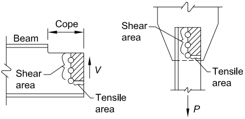
Figure description:
Topic: Failure surfaces for block shear rupture limit state (Fig. C-J4.1.
Key Information:
- Mechanism: Failure occurs by the physical tearing out of the shaded material regions.
- Left Diagram (Coped Beam:
- Force: Vertical shear force .
- Failure Surface: Consists of a vertical shear area along the bolt line and a horizontal tensile area extending to the edge.
- Right Diagram (Tension Member:
- Force: Axial tensile force .
- Failure Surface: Consists of a vertical shear area parallel to the force and a horizontal tensile area perpendicular to the force.
- Key Entities: Beam, cope, bolt holes (circles, shear area, tensile area, and applied forces ( and .
Fig. C-J4.1. Failure surface for block shear rupture limit state.
The Specification has adopted a conservative model to predict block shear strength. The mode of failure in coped beam webs and angles is different than that of gusset plates because the shear resistance is present on only one plane, in which case there must be some rotation of the block of material that is providing the total resistance.
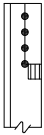
Although tensile failure is observed through the net section on the end plane, the distribution of tensile stresses is not always uniform (Ricles and Yura, 1983; Kulak and Grondin, 2001; Hardash and Bjorhovde, 1985). A reduction factor, , is included in Equation J4-5 to approximate the nonuniform stress distribution on the tensile plane. The tensile stress distribution is nonuniform in the two row connection in Figure C-J4.2(b) because the rows of bolts nearest the beam end pick up most of the shear load. For conditions not shown in Figure C-J4.2, may be taken as , where is the ratio of the eccentricity of the load to the centroid of the resistance divided by the block length. This fits data reported by Kulak and Grondin (2001), Kulak and Grondin (2002), and Yura et al. (1982).
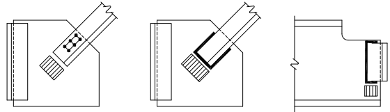
Figure description:
- Figure 1 (Left: Bolted diagonal brace connection to a gusset plate featuring a 2x3 bolt pattern. Cross-hatching indicates the predicted tension failure plane on the gusset plate.
- Figure 2 (Middle: Welded diagonal brace connection to a gusset plate utilizing a U-shaped weld. Cross-hatching denotes the potential block shear failure zone.
- Figure 3 (Right: Connection for a coped beam end. Cross-hatching identifies the critical failure planes at the connection interface.
Bolted Angle
Welded Angle
Welded Angle
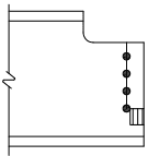
Figure description:
- Entity: Welded Angle Single-Row Beam End Connection.
- Structural Components:
- I-beam with a notched top flange.
- Vertical connection plate or angle attached to the web.
- Four vertically aligned circular fasteners (bolts or rivets.
- Rectangular weld symbol/fillet weld at the bottom of the connection.
Single-Row Beam End Connections
Angle Ends
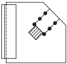
Figure description:
Key Entities & Information:
- Gusset Plate: The central, irregularly shaped flat plate serving as the connection point for structural members.
- Vertical Member: A structural element attached to the left side of the gusset plate.
- Diagonal Member (Angle: A structural angle oriented diagonally and connected to the gusset plate.
- Fasteners: Six black dots representing bolts or rivets arranged in two parallel rows of three, securing the diagonal member to the gusset plate.
- Structural Assembly: The diagram illustrates a typical connection detail involving "Angle Ends" joined via a "Gusset Plate."
Gusset Plates
(a) Cases for which
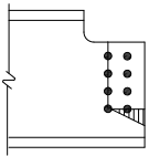
Figure description:
Diagram Details: Multiple-Row Beam-End Connection
- Type: Coped beam-end connection.
- Bolt Pattern: Two vertical rows of four bolts each (8 total.
- Design Parameter: , indicating a case for uniform tension stress distribution.
- Key Indicator: Hatched region at the base of the bolt group identifies the area of uniform tension stress for block shear calculations.
Multiple-Row Beam-End Connections
(b) Cases for which
Fig. C-J4.2. Block shear tensile stress distributions.
Block shear is a rupture or tearing phenomenon, not a yielding limit state. However, gross yielding on the shear plane can occur when tearing on the tensile plane commences if exceeds . Hence, Equation J4-5 limits the term to not greater than (Hardash and Bjorhovde, 1985). Equation J4-5 is consistent with the philosophy in Chapter D for tension members where the gross area is used for the limit state of yielding and the net area is used for the limit state of rupture.
J4.4 Strength of Elements in Compression
Specification Section E3 for flexural buckling of members was developed for designing main structural members with various cross-sectional shapes and residual stress patterns. Because connection elements have lower residual stresses and higher shape factors than main members, the buckling strength in the inelastic range is higher than predicted by the Specification equations for flexural buckling of members (Dowswell, 2016). To account for this behavior at low slenderness ratios, the nominal stress is taken as the specified minimum yield stress when the slenderness ratio is equal to or less than 25.
For wide gusset plates modeled as an equivalent column, the effective column width is based on the stress dispersion angle. As discussed in Commentary Section J4.1, the dispersion angle is partially dependent on the inelastic deformation capacity, which increases with decreasing plate slenderness (Dowswell, 2013a). In practice, the equivalent column width is generally calculated with a constant dispersion angle, which was based on the experimental stress trajectories in elastic gusset plates. In this case, the equivalent cross section is known as the Whitmore section (Whitmore, 1952).
Effective lengths, , have been developed for several common gusset plate geometries. In most cases, the effective length recommendations were calibrated for use with a dispersion angle; therefore, gusset plates are typically designed using an equivalent cross section defined by the Whitmore criterion. The equivalent column method is discussed further in Appendix C of AISC Design Guide 29, Vertical Bracing Connections-Analysis and Design (Muir and Thornton, 2014).
Because a corner gusset plate is restrained along two edges, it is difficult to establish either , the laterally unbraced length of the element, or , the effective length factor. Dowswell (2006) provides guidance for determining and based on empirical data. When the gusset is found to be compact, the slenderness ratio can be assumed to be less than or equal to 25 .
J4.5 Strength of Elements in Flexure
Affected and connecting elements are often short enough and thick enough that flexural effects, if present at all, do not impact the design. When such elements are long enough and thin enough that flexural effects must be considered, the AISC Steel Construction Manual (AISC, 2017) provides guidance relative to several specific conditions. Part 9 of the AISC Manual contains procedures to check the flexural strength of a coped beam. Part 9 also contains a discussion of prying action, which incorporates a weak-axis flexural strength check for framing-angle connections, endplate connections, flanges, and other similar elements. Part 10 contains procedures
to determine the flexural strength of plates used in the extended configuration of the single-plate shear connection. For all other conditions, the checks provided in Section F11 can be used.
The available flexural strength of connecting elements in LRFD can be calculated as the minimum of and , or in ASD as the minimum of and . Consequences of large deflections and supported member or plate instability must be considered when these values are used. If deflection is a concern, the factored loads should also be checked against for LRFD (Mohr and Murray, 2008).
Section F13.1 contains checks related to the strength reduction for members with bolt holes in the tension flange, which in some instances may be governed by net flexural rupture.