C-J2J2 Welds and welded joints
PDF page 547 · AISC 360-22
Provisions of this Specification related to welds are predicated on compliance with AWS D1.1/D1.1M, Structural Welding Code—Steel (AWS, 2020), hereafter referred to as AWS D1.1/D1.1M, except where those provisions differ from this Specification.
Examples of provisions in this Specification that vary from the AWS D1.1/D1.1M are as follows:
-
(a) Dimensions for weld access holes are defined differently. This Specification has a 1½ in. (38 mm) minimum access hole length.
-
(b) This Specification provides rules for permitting an increase in effective throat of fillet welds to account for penetration.
-
(c) This Specification permits taking the outside radius, R, of hollow structural sections (HSS) for the purpose of calculating the size of flare groove welds as twice the nominal thickness of the HSS. When R is less than 3/8 in. (10 mm), only the reinforcing over a flare bevel is counted for strength.
-
(d) Nominal stresses and permitted filler metal strength levels vary between this Specification and AWS D1.1/D1.1M.
-
(e) This Specification provides design and fabrication provisions and allowable cyclic stress ranges for categories of cyclically loaded connections, including some bolted connections.
-
(f) This Specification has provisions for reentrant corners for copes in beams.
-
(g) This Specification has provisions for cut surfaces of galvanized members, including grinding and inspection.
-
(h) This Specification has provisions regarding what inspections are required that are more explicit than the provisions of AWS D1.1/D1.1M.
Selection of weld type, complete-joint-penetration (CJP) groove weld, fillet weld, or partial-joint-penetration (PJP) groove weld, depends on base connection geometry (butt-joint versus T- or corner-joint), in addition to required strength, and other issues discussed in the following. Notch effects and the ability to evaluate with nondestructive testing may affect joint selection for cyclically loaded joints or joints expected to deform plastically.
J2.1 Groove Welds
J2.1a Effective Area
Tables J2.1 and J2.2 show that the effective throat of PJP and flare groove welds is dependent upon the weld process and the position of the weld. It is recommended that the design drawings show either the required strength or the required effective throat size and allow the fabricator to select the process and determine the position required to meet the specified requirements. Effective throats larger than those in Table J2.2 can be qualified by tests. Weld reinforcement is not used in determining the effective throat of a groove weld, but reinforcing fillets on T- and corner-joints are accounted for in the effective throat. See AWS D1.1/D1.1M, clause 4 (AWS, 2020).
J2.1b Limitations
Table J2.3 gives the minimum effective throat thickness of a PJP groove weld. Notice that for PJP groove welds Table J2.3 goes up to a plate thickness of over 6 in. (150 mm) and a minimum weld throat of 5/8 in. (16 mm), whereas for fillet welds, Table J2.4 goes up to a plate thickness of over 3/4 in. (19 mm) and a minimum leg size of fillet weld of only 5/16 in. (8 mm). The additional thickness for PJP groove welds is intended to provide for reasonable proportionality between weld and material thickness. The use of single-sided PJP groove welds in joints subjected to rotation about the toe of the weld is discouraged.
J2.2 Fillet Welds
J2.2a Effective Area
The effective throat of a fillet weld does not include the weld reinforcement, nor any penetration beyond the weld root. Some welding procedures produce a consistent penetration beyond the root of the weld. This penetration contributes to the strength of the weld. However, it is necessary to demonstrate that the weld procedure to be used produces this increased penetration. This is done for mechanized or automated procedures by welding a test joint and sectioning that joint in three places. Consistency of penetration along the joint is essential and the minimum penetration achieved is the maximum permitted to be considered in design of the weld.
J2.2b Limitations
Table J2.4 provides the minimum size of a fillet weld for a given thickness of the thinner part joined. The requirements are not based on strength considerations, but on the quench effect of thick material on small welds. Very rapid cooling of weld metal may result in a loss of ductility. Furthermore, the restraint to weld metal shrinkage provided by thick material may result in weld cracking.
The use of the thinner part to determine the minimum size weld is based on the prevalence of the use of filler metal considered to be “low hydrogen.” Because a 5/16 in. (8 mm) fillet weld is the largest that can be deposited in a single pass by the shielded metal arc welding (SMAW) process and still be considered prequalified under AWS D1.1/D1.1M, 5/16 in. (8 mm) applies to all material greater than 3/4 in. (19 mm) in thickness, but minimum preheat and interpass temperatures are required by AWS D1.1/D1.1M. The design drawings should reflect these minimum sizes and the production welds should reflect these minimum sizes.
For thicker members in lap joints, it is possible for the welder to melt away the upper corner, resulting in a weld that appears to be full size but actually lacks the required weld throat dimension as shown in Figure C-J2.1(a). On thinner members, the full weld throat is likely to be achieved, even if the edge is melted away. Accordingly, when the plate is 1/4 in. (6 mm) or thicker, the maximum fillet weld size is 1/16 in. (2 mm) less than the plate thickness, , which is sufficient so that the edge remains as shown in Figure C-J2.1(b).
By providing a minimum lap of five times the thickness of the thinner part of a lap joint, the resulting rotation of the joint when pulled will not be excessive, as shown in Figure C-J2.2, where the condition shown in the right-hand figure subjects the fillet weld to torsion. Fillet welded lap joints under tension tend to open and apply a tearing action at the root of the weld as shown in Figure C-J2.3(b), unless restrained by a force, , as shown in Figure C-J2.3(a). The minimum length reduces stresses due to Poisson effects.
The use of single-sided fillet welds in joints subjected to rotation around the toe of the weld is discouraged. End returns are not essential for developing the full length of fillet-welded connections and have a negligible effect on their strength. Their use has been encouraged so that the weld size is maintained over the length of the weld,
to enhance the fatigue resistance of cyclically loaded flexible end connections, and to increase the plastic deformation capability of such connections.
The weld strength database on which the Specification was developed had no end returns. This includes the study reported in Higgins and Preece (1968), the seat angle tests in Lyse and Schreiner (1935), the seat and top angle tests in Lyse and Gibson (1937), the tests on beam webs welded directly to a column or girder by fillet welds in Johnston and Deits (1942), and the tests on eccentrically loaded welded connections reported by Butler et al. (1972). Hence, the current strength values and joint
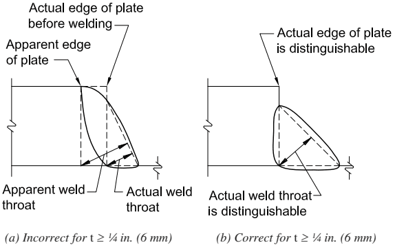
Figure description:
Fig. C-J2.1. Identification of plate edge
The diagrams illustrate welding standards for plate thicknesses :
- (a Incorrect: The weld melts the top corner of the plate, leading to an apparent edge and apparent weld throat that are larger than the actual edge and actual weld throat.
- (b Correct: The actual edge of the plate remains distinguishable, allowing the actual weld throat to be clearly identified and measured.
Fig. C-J2.1. Identification of plate edge.
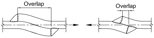
Figure description:
Fig. C-J2.2. Minimum lap
- Description: Engineering diagrams illustrating "Overlap" in welded lap joints.
- Key Entities:
- Plates: Two overlapping horizontal members.
- Fillet Welds: Triangular weld symbols joining the edge of one plate to the surface of another.
- Tension Arrows: Horizontal arrows indicating opposing forces pulling on the plates.
- Details:
- Dimension lines labeled "Overlap" specify the distance between the two weld lines.
- The left diagram shows a standard overlap.
- The right diagram shows a significantly smaller overlap, representing the "minimum lap" condition.
Fig. C-J2.2. Minimum lap.
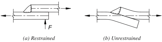
Figure description:
Diagrams illustrating lap joints under tension:
- (a Restrained: A lap joint held in place by an external force ( applied at the end of one plate, keeping the plates parallel and preventing rotation while under tensile stress (arrows pointing outwards.
- (b Unrestrained: A lap joint without external restraint, showing the plates bending and rotating out of plane due to the eccentric nature of the tensile load, resulting in deformation at the weld.
Fig. C-J2.3. Restraint of lap joints.
Specification for Structural Steel Buildings, August 1, 2022 AMERICAN INSTITUTE OF STEEL CONSTRUCTION
design models do not require end returns when the required weld size is provided. Johnston and Green (1940) noted that movement consistent with the design assumption of no end restraint (in other words, joint flexibility) was enhanced without end returns. They also verified that greater plastic deformation of the connection was achieved when end returns existed, although the strength was not significantly different.
When longitudinal fillet welds parallel to the stress are used to transmit the load to the end of an axially loaded member, the welds are termed “end-loaded.” Typical examples of such welds include, but are not limited to, (a) longitudinally welded lap joints at the end of axially loaded members, (b) welds attaching bearing stiffeners, and (c) similar cases. Typical examples of longitudinally loaded fillet welds that are not considered end-loaded include, but are not limited to, (a) welds that connect plates or shapes to form built-up cross sections in which the shear force is applied to each increment of length of weld depending upon the distribution of the shear along the length of the member and (b) welds attaching beam web connection angles and shear plates because the flow of shear force from the beam or girder web to the weld is essentially uniform throughout the weld length; that is, the weld is not end-loaded despite the fact that it is loaded parallel to the weld axis. Additionally, the reduction coefficient, , does not apply to welds attaching stiffeners to webs because the stiffeners and welds are not subjected to calculated axial stress but merely serve to keep the web flat.
The distribution of stress along the length of end-loaded fillet welds is not uniform and is dependent upon complex relationships between the stiffness of the longitudinal fillet weld relative to the stiffness of the connected materials. Experience has shown that when the length of the weld is equal to approximately 100 times the weld size or less, it is reasonable to assume that the full length is effective. As shown in Figure C-J2.4, for weld lengths greater than 100 times the weld size, the effective length should be taken as less than the actual length. The reduction factor, , provided in Section J2.2b is the equivalent to that given in CEN (2005a), which is a
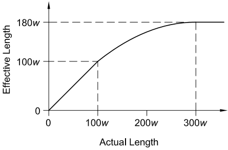
Figure description:
Relationship between Actual and Effective Length
Effective Length vs Actual Length
Annotations
- 100w intersection (dashed_line - position: x = 100w, y = 100w)
- 180w plateau (dashed_line - position: x = 300w, y = 180w)
| Actual Length | Effective Length |
|---|---|
| 0 | 0 |
| 100w | 100w |
| 200w | ~160w |
| 300w | 180w |
| > 300w | 180w |
Notes: The graph depicts a relationship where the Effective Length is equal to the Actual Length until it reaches 100w. Beyond 100w, the growth of the Effective Length slows down following a curve until it plateaus at a maximum value of 180w when the Actual Length reaches 300w.
Fig. C-J2.4. Effective weld length.
Specification for Structural Steel Buildings, August 1, 2022 AMERICAN INSTITUTE OF STEEL CONSTRUCTION
simplified approximation of exponential formulas developed by finite element studies and tests performed in Europe over many years. The provision is based on the combined consideration of the nominal strength for fillet welds with leg size less than in. ( 6 mm ) and of a judgment-based serviceability limit of slightly less than in. ( 1 mm ) displacement at the end of the weld for welds with leg size in. ( 6 mm ) and larger. Given the empirically derived mathematical form of the factor, as the ratio of weld length to weld size, , increases beyond 300 , the effective length of the weld begins to decrease, illogically causing a weld of greater length to have progressively less strength. Therefore, the effective length is taken as when the weld length is greater than 300 times the leg size.
In most cases, fillet weld terminations do not affect the strength or serviceability of connections. However, in certain cases the disposition of welds affects the planned function of the connection, and notches may affect the static strength and the resistance to crack initiation if cyclic loads of sufficient magnitude and frequency occur. For these cases, termination details at the end of the joint are specified to provide the desired profile and performance. In cases where profile and notches are less critical, terminations are permitted to run to the end. In most cases, stopping the weld short of the end of the joint will not reduce the strength of the weld. The small loss of weld area due to stopping the weld short of the end of the joint by one to two weld sizes is not typically considered in the calculation of weld strength. Only short weld lengths will be significantly affected by this.
The following situations require special attention:
- (1) For lapped joints where one part extends beyond the end or edge of the part to which it is welded and if the parts are subjected to calculated tensile stress at the start of the overlap, it is important that the weld terminate a short distance from the stressed edge. For one typical example, the lap joint between the tee chord and the web members of a truss, the weld should not extend to the edge of the tee stem (see Figure C-J2.5). The best technique to avoid inadvertent notches at this critical location is to strike the welding arc at a point slightly back from the
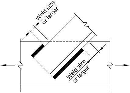
Figure description:
- Subject: Engineering diagram of fillet welds near tension edges (Fig. C-J2.5.
- Key Entities:
- Main Plate: Subjected to horizontal tension, indicated by arrows on the left and right.
- Attached Member: Rectangular element joined to the main plate at an angle.
- Fillet Welds: Represented by two thick black lines on opposing sides of the attached member.
- Critical Dimensions:
- The distance from the end of each weld to the edge of the adjacent plate is labeled as "Weld size or larger."
Fig. C-J2.5. Fillet welds near tension edges.
Specification for Structural Steel Buildings, August 1, 2022 AMERICAN INSTITUTE OF STEEL CONSTRUCTION
edge and proceed with welding in the direction away from the edge (see Figure C-J2.6). Where framing angles extend beyond the end of the beam web to which they are welded, the free end of the beam web is subjected to zero stress; thus, it is permissible for the fillet weld to extend continuously across the top end, along the side, and along the bottom end of the angle to the extreme end of the beam (see Figure C-J2.7).
(2) For connections such as framing angles and framing tees, which are assumed in the design of the structure to be flexible connections, the tension edges of the outstanding legs or flanges must be left unwelded over a substantial portion of their length to provide flexibility in the connection. Tests have shown that the static strength of the connection is the same with or without end returns; therefore, the use of returns is optional, but if used, their length must be restricted to not more than four times the weld size (Johnston and Green, 1940) (see Figure C-J2.8).
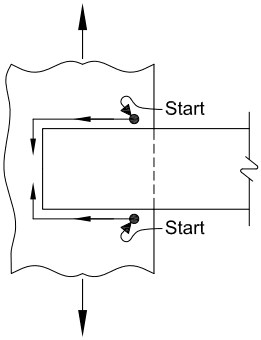
Figure description:
Key Information: Fig. C-J2.6
- Subject: Suggested welding travel direction to avoid notches in structural connections.
- Entities:
- Main Member: Large vertical plate undergoing tension (indicated by vertical arrows.
- Attached Member: Horizontal plate or angle leg welded to the main member.
- Weld Path: Arrows indicate welding starts away from the corner, moves toward the corner, and then turns the corner.
- Start Points: Specific locations identified where the weld begins to ensure continuity around the corner.
- Purpose: Illustrates proper technique for applying fillet welds around the ends of plates to prevent stress concentrations (notches at the corners.
Fig. C-J2.6. Suggested direction of welding travel to avoid notches.
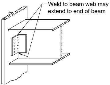
Figure description:
- Subject: Fillet weld details on framing angles for a beam-to-column connection.
- Key Note: The weld connecting the framing angle to the beam web may extend to the end of the beam.
- Components:
- Steel I-beam (web and flanges.
- Framing angle with pre-drilled holes.
- Vertical support member (column.
- Fillet welds at the top and bottom of the framing angle connection to the beam web.
Fig. C-J2.7. Fillet weld details on framing angles.
- (3) Experience has shown that when ends of intermediate transverse stiffeners on the webs of plate girders are not welded to the flanges (the usual practice), small torsional distortions of the flange occur near shipping bearing points in the normal course of shipping by rail or truck and may cause high out-of-plane bending stresses (up to the yield point) and fatigue cracking at the toe of the web-to-flange welds. This has been observed even with closely fitted stiffeners. The intensity of these out-of-plane stresses may be effectively limited and cracking prevented if “breathing room” is provided by terminating the stiffener weld away from the web-to-flange welds. The unwelded distance should not exceed six times the web thickness so that column buckling of the web within the unwelded length does not occur.
- (4) For fillet welds that occur on opposite sides of a common plane, it is difficult to deposit a weld continuously around the corner from one side to the other without causing a gouge in the corner of the parts joined; therefore, the welds must be interrupted at the corner (see Figure C-J2.9). AWS D1.1/D1.1M includes a specific exception that permits continuous welds around opposite sides of a common plane where the engineer requires sealed joints.
J2.3 Plug and Slot Welds
A plug weld is a weld made in a circular hole in one member of a joint fusing that member to another member. A slot weld is a weld made in an elongated hole in one member of a joint fusing that member to another member. Both plug and slot welds are only applied to lap joints. Care should be taken when plug or slot welds are applied to structures subjected to cyclic loading as the fatigue performance of these welds is limited.
A fillet weld inside a hole or slot is not a plug weld. A puddle weld, typically used for joining decking to the supporting steel, is not the same as a plug weld.
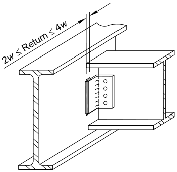
Figure description:
- Subject: Flexible steel beam-to-beam connection using a welded angle.
- Key Feature: Weld returns at the top of the connection angle.
- Design Rule: The length of the weld return must satisfy (where is the weld size.
- Requirement: Returns are optional for flexible connections unless they are subject to fatigue.
- Contextual Note: Fillet welds in holes/slots and puddle welds for decking are distinct from plug welds.
Fig. C-J2.8. Flexible connection returns optional unless subject to fatigue.
Specification for Structural Steel Buildings, August 1, 2022 AMERICAN INSTITUTE OF STEEL CONSTRUCTION
J2.3a Effective Area
When plug and slot welds are detailed in accordance with Section J2.3b, the strength of the weld is controlled by the size of the fused area between the weld and the base metal. The total area of the hole or slot is used to determine the effective area.
J2.3b Limitations
Plug and slot welds are limited to situations where they are loaded in shear or where they are used to prevent elements of a cross section from buckling, such as for web doubler plates on deeper rolled sections. Plug and slot welds are only allowed where the applied loads result in shear between the joined materials—they are not to be used to resist direct tensile loads. This restriction does not apply to fillets in holes or slots.
The geometric limitations on hole and slot sizes are prescribed in order to provide a geometry that is conducive to good fusion. Deep, narrow slots and holes make it difficult for the welder to gain access and see the bottom of the cavity into which weld metal must be placed. Where access is difficult, fusion may be limited and the strength of the connection reduced.
J2.4 Strength
The strength of welds is governed by the strength of either the base material or the deposited weld metal. Table J2.5 presents the nominal weld strengths and the and factors, as well as the limitations on filler metal strength levels.
The strength of a joint that contains a complete-joint-penetration (CJP) groove weld, whether loaded in tension or compression, is dependent upon the strength of the base metal and no computation of the strength of the CJP groove weld is required. For tension applications, matching strength filler metal is required, as defined in AWS D1.1/ D1.1M, Table 5.4. For compression applications, up to a 10 ksi (69 MPa) decrease in filler metal strength is permitted, which is equivalent to one strength level.
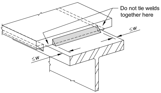
Figure description:
Key Information: Fillet Weld Details (Fig. C-J2.9
- Entities:
- Base Metal: A horizontal plate overlapping a T-shaped section.
- Fillet Welds: Located on opposite sides of a common plane where the plate edges meet the T-section flange.
- Geometric Requirements:
- Weld Setback: The welds must terminate at a distance (where is the weld size from the edge of the common plane.
- Constraint: A specific instruction indicates: "Do not tie welds together here," referencing the gap between the two weld segments across the common plane.
Fig. C-J2.9. Details for fillet welds that occur on opposite sides of a common plane.
CJP groove welds loaded in tension or compression parallel to the weld axis, such as for the groove-welded corners of box columns, do not transfer primary loads across the joint. In cases such as this, no computation of the strength of the CJP groove weld strength is required.
CJP groove-welded tension joints are intended to provide strength equivalent to the base metal; therefore, matching filler metal is required. CJP groove welds have been shown not to exhibit compression failure even when they are undermatched. The amount of undermatching before unacceptable deformation occurs has not been established, but one standard strength level is conservative and therefore permitted. Joints in which the weld strength is calculated based on filler metal classification strength can be designed using any filler metal strength equal to or less than matching. Filler metal selection is still subject to compliance with AWS D1.1/D1.1M.
Connections that contain partial-joint-penetration (PJP) groove welds designed to bear in accordance with Section J1.4(b), and where the connection is loaded in compression, are not limited in strength by the weld because the surrounding base metal can transfer compression loads. When not designed in accordance with Section J1.4(b), an otherwise similar connection must be designed considering the possibility that either the weld or the base metal may be the critical component in the connection.
The factor of 0.6 on for the tensile strength of PJP groove welds has been used since the early 1960 s to compensate for factors such as the notch effect of the unfused area of the joint and uncertain quality in the root of the weld because PJP groove welds are typically not subjected to nondestructive evaluation. It does not imply that the tensile failure mode is by shear stress on the effective throat, as is the case with fillet welds.
The nominal strength of PJP groove-welded joints in compression is higher than for joints in tension or shear because the compression limit states are not observed on weld metal until significantly above the yield strength. Further, as the PJP groove weld deforms, bearing on the unfused surface of the joint eventually occurs and compression loads can be transferred through this interface. Column splices have historically been connected with relatively small PJP groove welds. Compressive stress is not a design consideration for these PJP welds when the connection meets the requirements of Section J1.4(a). These connections are in compression, adequately braced, and designed to bear. Section M4.4 recognizes that, in the as-fitted condition, the contact may not be consistent across the joint and therefore rules are provided to assure some contact that limits the potential deformation of weld metal and the surrounding material. Therefore, the compressive stress in the weld metal does not need to be considered per the requirements of Section J1.4(b). When compression members other than columns are designed to bear per the requirements of Section J1.4(b), the compression stress in the PJP welds may also be neglected. All PJP compression joints should also be proportioned to resist any tension developed by the load combinations stipulated in Section B2 and as may be required in Section J1.4(b).
In Table J2.5, the nominal strength of fillet welds is determined from the effective throat area, whereas the strengths of the connected parts are governed by their respective thicknesses. Figure C-J2.10 illustrates the shear planes for fillet welds and base material:
- (a) Plane 1-1, in which the strength is governed by the shear strength of material A
- (b) Plane 2-2, in which the strength is governed by the shear strength of the weld metal
- (c) Plane 3-3, in which the strength is governed by the shear strength of material B
The strength of the welded joint is the lowest of the strengths calculated in each plane of shear transfer. Note that planes 1-1 and 3-3 are positioned away from the fusion areas between the weld and the base material. Tests have demonstrated that the stress on this fusion area is not critical in determining the shear strength of fillet welds (Preece, 1968).
The shear planes for plug and PJP groove welds are shown in Figure C-J2.11 for the weld and base metal. Generally, the base metal will govern the shear strength.
The instantaneous center of rotation method is a valid approach to calculate the strength of weld groups consisting of elements oriented in various directions relative to the load. The instantaneous center of rotation method considers strain compatibility among the elements in the weld group. Aspects of the method were previously included in the Specification. These aspects along with a more comprehensive explanation of the method are discussed in the AISC Steel Construction Manual (AISC, 2017).
Welds to HSS are inherently single-sided. Experimental testing and numerical studies have been performed on fillet-welded joints to the ends of HSS members, where the HSS end is connected to a thick, rigid plate and the HSS is subjected to axial tension (Packer et al., 2016; Tousignant and Packer, 2016, 2017b). In such situations, the entire weld length is effective due to the rigid base material. This research has shown that single-sided welds to a tension-loaded HSS wall element are partially unrestrained and are prone to local bending about the axis of the weld, as shown
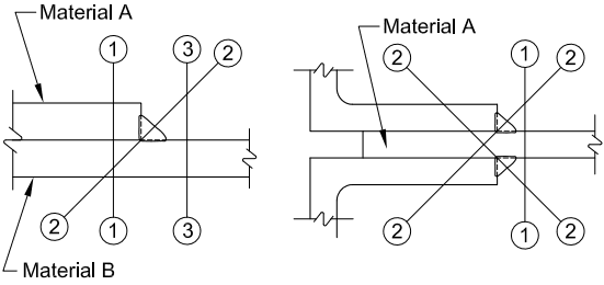
Figure description:
Entities:
- Material A: Structural component (e.g., HSS or plate being welded.
- Material B: Base material or plate to which Material A is joined.
- Fillet Welds: Triangular joints connecting the two materials.
- Shear Planes (Numbered Lines:
- 1: Vertical shear plane through the base material.
- 2: Diagonal shear plane through the weld throat.
- 3: Vertical shear plane through the adjacent connected material.
Key Information:
- The diagram illustrates potential failure paths (shear planes for fillet welds subjected to longitudinal shear.
- Left Image: Single-sided fillet weld joint between Material A and Material B.
- Right Image: Double-sided (symmetric fillet weld joint involving an HSS-type member or similar structural shape.
- The numbered callouts identify critical cross-sections where shear capacity is typically evaluated.
Fig. C-J2.10. Shear planes for fillet welds loaded in longitudinal shear.
in Figure C-J2.12, leading to opening of the weld root. The restraint provided to the fillet weld depends on the connected element thickness and shape (linear versus curved), as well as the weld size and amount of penetration. It was found that the HSS welded joints in this research did not achieve the expected target reliability (safety) index of (Specification Commentary B3.1) at failure, if the directional strength increase factor, , was applied. Thus, this factor of should be set to unity (in other words, taken as zero) for fillet welds at the ends of rectangular, tension-loaded HSS wall elements. The single-sided weld effect was more severe for square and rectangular HSS than for round HSS. Because recent numerical research (Tousignant and Packer, 2017a) found that round HSS-to-rigid plate connections generated , which is only marginally lower than the target of , fillet welds to the ends of tension-loaded round HSS have been excluded from the prohibition on the use of the directional strength increase factor.
Use of the directional strength increase factor is not permitted for fillet welds to the ends of square and rectangular HSS in which any face is in tension, when the design approach is to develop the yield strength of the connected HSS wall, nor when the design is a “fit-for-purpose” approach. The latter is covered in Section K5 and entails
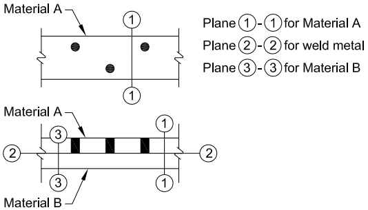
Figure description:
Key Entities and Details:
- Subject: Structural diagram of plug welds joining two materials.
- Materials:
- Material A: Top plate or member.
- Material B: Bottom plate or member.
- Failure/Shear Planes:
- Plane 1-1: Vertical cross-section through Material A.
- Plane 2-2: Longitudinal shear plane through the weld metal (interface between Material A and B.
- Plane 3-3: Vertical cross-section through Material B.
- Visual Components:
- Top view shows circular plug welds.
- Side view shows the weld metal connecting Material A and Material B across the interface.
(a) Plug welds
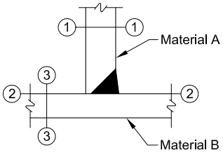
Figure description:
Technical Diagram: Partial-Joint-Penetration Groove Weld
- Key Entities:
- Material A: Vertical structural member.
- Material B: Horizontal base member forming a T-joint with Material A.
- Weld: Solid black triangular region indicating a partial-joint-penetration groove weld at the junction.
- Reference Markers:
- ①: Horizontal cross-section through Material A.
- ②: Vertical planes at the boundaries of Material B.
- ③: Vertical cross-section through Material B.
(b) Partial-joint-penetration groove welds
Fig. C-J2.11. Shear planes for plug and partial-joint-penetration groove welds.
the use of weld effective lengths. Those provisions have been shown to generate suitable target reliability (safety) indices for welded joints to square and rectangular HSS with faces in tension, in conjunction with the weld effective lengths advocated and without the directional strength increase factor (McFadden and Packer, 2014; Tousignant and Packer, 2015). Use of the directional strength increase factor is permitted for double-sided fillet welds to longitudinal or transverse plate branches attached to HSS, regardless of branch loading. The fillet weld directional strength increase factor is also permitted for HSS branches to HSS chords, where all of the branch remains in compression.
J2.5 Combination of Welds
When determining the strength of a combination PJP groove weld and fillet weld contained within the same joint, the total throat dimension is not the simple addition of the fillet weld throat and the groove weld throat. In such cases, the resultant throat of the combined weld (shortest dimension from the root to face of the final weld) must be determined and the design based upon this dimension.
J2.6 Filler Metal Requirements
Applied and residual stresses and geometrical discontinuities from backing bars with associated notch effects contribute to sensitivity to fracture. Additionally, some weld metals in combination with certain procedures result in welds with low notch toughness. Accordingly, this Specification requires a minimum specified toughness for weld metals in those joints that are subjected to more significant applied stresses and toughness demands. The level of toughness required is selected as one level more conservative than the base metal requirement for hot-rolled shapes with a flange thickness exceeding 2 in. (50 mm).
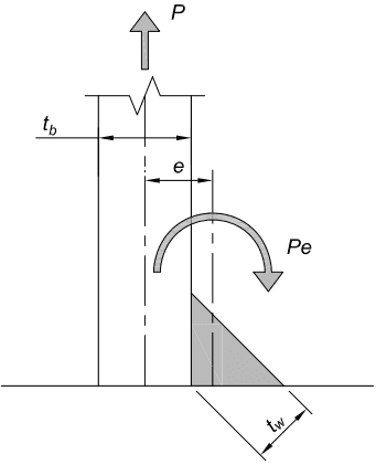
Figure description:
Key Entities and Information:
- : Applied tensile load.
- : Eccentricity (distance between the line of action of the load and the weld throat.
- : Local bending moment caused by the eccentric load.
- : Thickness of the base metal plate.
- : Effective throat thickness of the single-sided fillet weld.
- Mechanical Behavior: The diagram illustrates how an eccentric load creates local bending in a single-sided fillet weld joint.
Fig. C-J2.12. Eccentric loading on a single-sided fillet weld resulting in local bending.
J2.7 Mixed Weld Metal
Problems can occur when incompatible weld metals are used in combination and notch-tough composite weld metal is required. For instance, tack welds deposited using a self-shielded process with aluminum deoxidizers in the electrodes and subsequently covered by SAW weld passes can result in a composite weld metal with low notch toughness, despite the fact that each process by itself could provide notch-tough weld metal.
Potential concern about intermixing weld metal types is limited to situations where one of the two weld metals is deposited by the self-shielded flux-cored arc welding (FCAW-s) process. Changes in tensile and elongation properties have been demonstrated to be of insignificant consequence. Notch toughness is the property that can be affected the most. Many compatible combinations of FCAW-s and other processes are commercially available.