C-E2E2 Effective length
PDF page 422 · AISC 360-22
In the 2016 AISC Specification (AISC, 2016), the effective length, which since the 1963 AISC Specification (AISC, 1963) had been given as , was changed to . This was done to simplify the definition of effective length for the various modes of buckling without having to define a specific effective length factor, . The effective
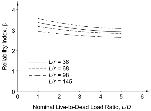
Figure description:
Reliability Index, vs Nominal Live-to-Dead Load Ratio,
Legend
- L/r = 38 — color: black; symbol: Solid line
- L/r = 68 — color: black; symbol: Dashed line
- L/r = 98 — color: black; symbol: Long dashed line
- L/r = 145 — color: black; symbol: Dash-dot line
| Nominal Live-to-Dead Load Ratio, | Reliability Index, () | Reliability Index, () | Reliability Index, () | Reliability Index, () |
|---|---|---|---|---|
| 1 | 3.35 | 3.18 | 2.92 | 3.55 |
| 2 | 3.18 | 3.02 | 2.82 | 3.32 |
| 3 | 3.05 | 2.92 | 2.75 | 3.22 |
| 4 | 2.98 | 2.88 | 2.68 | 3.15 |
| 5 | 2.92 | 2.82 | 2.65 | 3.08 |
Notes: The Reliability Index, is plotted against the Nominal Live-to-Dead Load Ratio, , for different values of .
Fig. C-E1.1. Reliability of columns (LRFD).
Specification for Structural Steel Buildings, August 1, 2022 AMERICAN INSTITUTE OF STEEL CONSTRUCTION
length is then defined as in those situations where effective length factors, , are appropriate. This change recognized that there are several ways to determine the effective length that do not involve the direct determination of an effective length factor. It also recognized that for some modes of buckling, such as torsional and flexural-torsional buckling, the traditional use of is not the best approach. The direct use of effective length without the -factor can be seen as a return to the approach used in the 1961 AISC Specification (AISC, 1961), when column strength equations based on effective length were first introduced by AISC.
The concept of a maximum limiting slenderness ratio has experienced an evolutionary change from a mandatory “...The slenderness ratio, , of compression members shall not exceed 200...” in the 1978 AISC Specification (AISC, 1978) to no restriction at all in the 2005 AISC Specification (AISC, 2005b). The 1978 ASD and the 1999 LRFD Specifications (AISC, 2000b) provided a transition from the mandatory limit to a limit that was defined in the 2005 AISC Specification by a User Note, with the observation that “...the slenderness ratio, , preferably should not exceed 200 ” However, the designer should keep in mind that compression members with a slenderness ratio of more than 200 will have a drastically reduced capacity, with nominal stress, , (Equation E3-3) less than 6.3 ksi (43 MPa). Although not strictly a design requirement, the advisory upper limit on slenderness ratio provides a minimum compressive strength.
A compression member with a high slenderness ratio may deflect due to its self- weight and lead to aesthetic, stability, or serviceability concerns. For example, exposed slender brace members may exhibit unsightly sagging due to member self-weight. Sagging will produce flexural stresses and, thus, reduce the available compressive strength. An upper limit on member slenderness, based on professional judgment and practical considerations of economics, further eases handling and mini- mizes inadvertent damage during fabrication, transport, and erection. Even minor
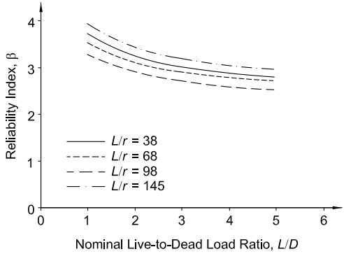
Figure description:
Reliability Index vs. Nominal Live-to-Dead Load Ratio
Reliability Index vs. Nominal Live-to-Dead Load Ratio
Legend
- L/r = 38 — color: black; symbol: Solid line
- L/r = 68 — color: black; symbol: Short dashed line
- L/r = 98 — color: black; symbol: Long dashed line
- L/r = 145 — color: black; symbol: Dash-dotted line
| Nominal Live-to-Dead Load Ratio, | Reliability Index, () | Reliability Index, () | Reliability Index, () | Reliability Index, () |
|---|---|---|---|---|
| 1.0 | 3.75 | 3.55 | 3.30 | 3.95 |
| 2.0 | 3.20 | 3.05 | 2.85 | 3.40 |
| 3.0 | 3.00 | 2.90 | 2.70 | 3.15 |
| 4.0 | 2.90 | 2.80 | 2.60 | 3.05 |
| 5.0 | 2.85 | 2.75 | 2.55 | 3.00 |
Fig. C-E1.2. Reliability of columns (ASD).
Specification for Structural Steel Buildings, August 1, 2022 AMERICAN INSTITUTE OF STEEL CONSTRUCTION
damage in slender compression members could reduce the already limited capacity and potentially result in failure at loads less than those considered in design. Slender members may exhibit noisy vibrations when subjected to wind forces, as in an open truss or when supporting vibrating equipment such as fans or compressors, and under even minor wind or seismic loading may result in “slapping” with cyclic buckling. The advisory upper limit of 300 for the slenderness ratio is based on the fabricated length of the member and the minimum radius of gyration of the section. Columns in building structures, for example, are often fabricated in multi-story lengths. For these reasons, it may be advantageous to specify members not exceeding the limit of 300. Engineering judgment should be used to determine whether or not to apply the limit; if not, steps must be taken to eliminate the serviceability problems, and special care should be exercised by the fabricator and erector to protect the structural integrity of the member.
Conformance with these limits does not guarantee that these detrimental conditions will not occur, but experience has shown that they can be significantly mitigated by conforming to these limits. For single angles, the radius of gyration about the z-axis produces the maximum and, except for very unusual support conditions, the maximum effective slenderness ratio.