C-E4E4 Torsional and flexural-torsional buckling of single angles and members without slender elements
PDF page 426 · AISC 360-22
Section E4 applies to singly symmetric and unsymmetric members and certain doubly symmetric members, such as cruciform or built-up columns with all nonslender elements, as defined in Section B4 for uniformly compressed elements. It also applies to doubly symmetric members when the torsional buckling length is greater than the flexural buckling length of the member. In addition, Section E4 applies to single angles with , although there are no ASTM A36/A36M hot-rolled angles for which this applies; for angles with and greater, this section may apply.
The equations in Section E4 for determining the torsional and flexural-torsional elastic buckling loads of columns are derived in textbooks and monographs on structural stability (Bleich, 1952; Timoshenko and Gere, 1961; Galambos, 1968a; Chen and Atsuta, 1977; Galambos and Surovek, 2008; and Ziemian, 2010). Because these equations apply only to elastic buckling, they must be modified for inelastic buckling by the appropriate equations of Section E3. Inelasticity has a more significant impact on warping torsion than St. Venant torsion. For consideration of inelastic effects, the full elastic torsional or flexural-torsional buckling stress is conservatively used to determine for use in the column equations of Section E3.
Torsional buckling of symmetric shapes and flexural-torsional buckling of unsymmetrical shapes are failure modes usually not considered in the design of hot-rolled columns. They generally do not govern, or the critical load differs very little from the minor-axis flexural buckling load. Torsional and flexural-torsional buckling modes may, however, control the strength of symmetric columns manufactured from relatively thin plate elements and unsymmetric columns and symmetric columns having torsional unbraced lengths significantly larger than the minor-axis flexural unbraced lengths.
Equations for determining the elastic critical stress for columns are given in Section E4. Table C-E4.1 serves as a guide for selecting the appropriate equations. Equation E4-4 is the general buckling expression that is applicable to doubly symmetric, singly symmetric, and unsymmetric shapes. Equation E4-3 was derived from Equation E4-4 for the specific case of a singly symmetric shape in which the y-axis is the axis of symmetry (such as in WT sections). For members, such as channels, in which the x-axis is the axis of symmetry, in Equation E4-3 should be replaced with .
For doubly symmetric shapes, the geometric centroid and shear center coincide resulting in . Therefore, for a doubly symmetric section, Equation E4-4
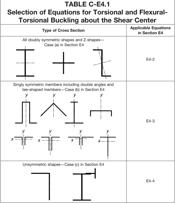
Figure description:
TABLE C-E4.1 Selection of Equations for Torsional and Flexural-Torsional Buckling about the Shear Center
Selection of Equations for Torsional and Flexural-Torsional Buckling about the Shear Center
| Type of Cross Section | Applicable Equations in Section E4 |
|---|---|
| All doubly symmetric shapes and Z-shapes—Case (a in Section E4) | E4-2 |
| Singly symmetric members including double angles and tee-shaped members—Case (b in Section E4) | E4-3 |
| Unsymmetric shapes—Case (c in Section E4) | E4-4 |
Notes: The table illustrates various cross-sectional shapes associated with each category. Case (a includes doubly symmetric I-beams, crosses, and Z-shapes. Case (b includes singly symmetric shapes like hat sections, channels, tees, and double angles. Case (c includes unsymmetric shapes like L-angles.)))
results in three roots: flexural buckling about the x-axis, flexural buckling about the y-axis, and torsional buckling about the shear center of the section, with the lowest root controlling the capacity of the cross section. Most designers are familiar with evaluating the strength of a wide-flange column by considering flexural buckling about the x-axis and y-axis; however, torsional buckling as given by Equation E4-2 is another potential buckling mode that should be considered and may control when the unbraced length for torsional buckling exceeds the unbraced length for minor- axis flexural buckling. Equation E4-2 is applicable for columns that twist about the shear center of the section, which will be the case when lateral bracing details like that shown in Figure C-E4.1 are used. The rod that is used for the brace in this case restrains the column from lateral movement about the minor axis, but does not generally prevent twist of the section and therefore the unbraced length for torsional
buckling may be larger than for minor-axis flexure, which is a case where torsional buckling may control. Most typical column base plate details will restrain twist at the base of the column. In addition, twist will often also be adequately restrained by relatively simple framing to beams. Many of the cases where inadequate torsional restraint is provided at a brace point will often occur at intermediate (between the ends of the column) brace locations.
Many common bracing details may result in situations where the lateral bracing is offset from the shear center of the section, such as columns or roof trusses restrained by a shear diaphragm that is connected to girts or purlins on the outside of the column or chord flange. Depending on the orientation of the primary member, the bracing may be offset along either the minor axis or the major axis as depicted in Figure C-E4.2. Because girts or purlins often have relatively simple connections, they do not restrain twist of the members; thus, columns or truss chords can be susceptible to a combination of torsional buckling and flexural buckling. In these cases, due to the offset of the bracing relative to the shear center, the members are susceptible to constrained-axis torsional buckling.
Timoshenko and Gere (1961) developed the following expressions for constrained-axis torsional buckling.
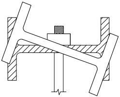
Figure description:
Key Information:
- Subject: Lateral bracing detail for I-shaped structural members.
- Action: Illustrates torsional buckling with twist occurring about the shear center.
- Components:
- Two overlapping I-beams: one horizontal (hatched and one rotated.
- Central vertical fastening rod with a nut and washer assembly.
- Vertical side constraints represented by hatched rectangular boundaries.
- Context: Engineering diagram used to model constrained-axis torsional buckling behavior as described by Timoshenko and Gere (1961.
Fig. C-E4.1. Lateral bracing detail resulting in twist about the shear center.
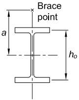
Figure description:
Key Entities and Information:
- I-beam cross-section: Shows a standard structural steel I-shape with flanges and a web.
- Brace point: Marked with an "x" above the top flange on the vertical centerline.
- Dimension : Vertical distance from the brace point to the horizontal shear center axis.
- Dimension : Vertical distance between the mid-thickness of the top and bottom flanges.
- Context: Illustrates a lateral bracing detail that results in twist about the shear center.
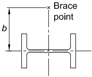
Figure description:
- Subject: I-beam (H-beam cross-section diagram.
- Key Entity: Brace point, located along the vertical centerline.
- Dimension: represents the bracing offset distance from the horizontal minor axis to the brace point.
(a) Bracing offset along minor axis
(b) Bracing offset along major axis
Fig. C-E4.2. Bracing details resulting in an offset relative to the shear center.
Bracing offset along the minor axis by an amount [see Figure C-E4.2(a)] as follows:
(C-E4-1)
Bracing offset along the major axis by an amount [see Figure C-E4.2(b)] as fol- lows:
(C-E4-2)
where the polar radius of gyration is given by the following expression:
(C-E4-3)
The terms in these equations are as defined in Section E4 with the exception of , and . The bracing offsets, and , are measured relative to the shear center. These are taken as and , respectively, in Equations E4-10, E4-11, and E4-12. The variable is the distance between flange centroids as indicated in Figure C-E4.2. The torsional effective length, , is the length between points where torsional rotation is restrained. The empirical factor was included to address some of the assumptions made in the original derivation. The expressions from Timoshenko and Gere (1961) were developed assuming that continuous lateral restraint was provided that is infinitely stiff. The impact of the continuous bracing assumption is not that significant because the column will generally be checked for buckling between discrete brace points. However, the assumption of the infinitely stiff lateral bracing will result in a reduction in the capacity for systems with finite brace stiffness. The -factor that is shown in Equations C-E4-1 and C-E4-2 is included to account for the reduction due to a finite brace stiffness. With a modest brace stiffness (such as stiffness values recommended in the Appendix 6 lateral bracing provisions), the reduction is relatively small and a value of 0.9 is recommended based upon finite element studies (Errera, 1976; Helwig and Yura, 1999). The -factor is taken as 1.0 here with little loss of accuracy.
It is important to recognize that as a lateral brace is moved away from the shear center, it permits the flexural buckling stiffness to interact with the torsional buckling stiffness to yield a constrained-axis torsional buckling strength less than the pure torsional buckling strength had the brace not existed. Figure C-E4.3 shows that, for a column with lateral and torsional restraint at the ends only and lateral bracing at mid-height, the torsional strength is greatest when the lateral brace is located at the shear center and diminishes, approaching the weak-axis flexural buckling strength for a column with effective length equal to , as the lateral brace moves away from the shear center.
The specific method of calculating the buckling strength of double-angle and tee-shaped members that had been given in the 2010 AISC Specification (AISC, 2010) was deleted in the 2016 AISC Specification (AISC, 2016) in preference for the use of the general flexural-torsional buckling equations because the deleted equation was usually more conservative than necessary.
Equations E4-2, E4-7, E4-10, and E4-12 contain a torsional buckling effective length, . This effective length may be conservatively taken as the length of the column. For greater accuracy, if both ends of the column have a connection that restrains warping, say by boxing the end over a length at least equal to the depth of the member, the effective length may be taken as 0.5 times the column length. If one end of the member is restrained from warping and the other end is free to warp, then the effective length may be taken as 0.7 times the column length.
At points of bracing both lateral and/or torsional bracing shall be provided, as required in Appendix 6. AISC Design Guide 9, Torsional Analysis of Structural Steel Members (Seaburg and Carter, 1997), provides an overview of the fundamentals of torsional loading for structural steel members. Design examples are also included.