C-E5E5 Single-angle compression members
PDF page 430 · AISC 360-22
The compressive strength of single angles is to be determined in accordance with Sections E3 or E7 for the limit state of flexural buckling and Section E4 for the limit state of flexural-torsional buckling. However, single angles with b t ≤0 71 . E Fy do not require consideration of flexural-torsional buckling according to Section E4. This applies to all currently produced hot-rolled angles with Fy = 36 ksi (250 MPa) but does not apply to all angles when Fy > 36 ksi (250 MPa). Use Section E4 to compute Fe for single angles only when b t > 0 71 . E Fy .
Section E5 also provides a simplified procedure for the design of single angles subjected to an axial compressive load introduced through one connected leg as discussed by Lutz (2006). The angle is treated as an axially loaded member by adjusting the member slenderness. The attached leg is to be attached to a gusset plate or the
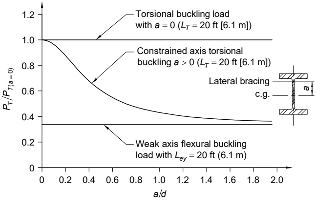
Figure description:
Buckling Load Ratios
Effect of Constraint Position on Torsional Buckling Load
Legend
- Torsional buckling load with a = 0 (L_T = 20 ft [6.1 m — color: black; symbol: Solid horizontal line at y=1.0
- Constrained axis torsional buckling a > 0 (L_T = 20 ft [6.1 m — color: black; symbol: Decaying curve
- Weak axis flexural buckling load with L_ey = 20 ft (6.1 m — color: black; symbol: Solid horizontal line at y≈0.34
Annotations
- Torsional buckling load with a = 0 (L_T = 20 ft [6.1 m (text_label - position: y = 1.0))
- Constrained axis torsional buckling a > 0 (L_T = 20 ft [6.1 m (text_label - position: Centered on decaying curve))
- Weak axis flexural buckling load with L_ey = 20 ft (6.1 m (text_label - position: y = 0.34))
| a/d | Torsional buckling load with a = 0 () ft [6.1 m | Constrained axis torsional buckling a > 0 () ft [6.1 m | Weak axis flexural buckling load with ft (6.1 m) |
|---|---|---|---|
| 0.0 | 1.0 | 1.00 | 0.34 |
| 0.2 | 1.0 | 0.94 | 0.34 |
| 0.4 | 1.0 | 0.76 | 0.34 |
| 0.6 | 1.0 | 0.59 | 0.34 |
| 0.8 | 1.0 | 0.49 | 0.34 |
| 1.0 | 1.0 | 0.43 | 0.34 |
| 1.2 | 1.0 | 0.39 | 0.34 |
| 1.4 | 1.0 | 0.37 | 0.34 |
| 1.6 | 1.0 | 0.36 | 0.34 |
| 1.8 | 1.0 | 0.35 | 0.34 |
| 2.0 | 1.0 | 0.34 | 0.34 |
Notes: The chart shows the normalized buckling load as a function of the ratio , where 'a' is the distance from the center of gravity (c.g. to the lateral bracing, and 'd' is the section depth. A cross-section diagram of an I-beam is provided on the right to illustrate these variables.))
Fig. C-E4.3. Torsional buckling capacity with lateral bracing offset along the weak axis, W16×26 (W410×38.8), L = 20 ft (6.1 m).
projecting leg of another member by welding or by a bolted connection with at least two bolts. The equivalent slenderness expressions in this section presume significant restraint about the axis, which is perpendicular to the connected leg. This leads to the angle member tending to bend and buckle primarily about the axis parallel to the attached gusset. For this reason, is the slenderness parameter used, where the subscript, , represents the axis parallel to the attached leg. This may be the - or -axis of the angle, depending on which leg is the attached leg. The modified slenderness ratios indirectly account for bending in the angles due to the eccentricity of loading and for the effects of end restraint from the members to which they are attached.
The equivalent slenderness expressions also presume a degree of rotational restraint. Equations E5-3 and E5-4 [Section E5(b), referred to as case (b)] assume a higher degree of rotational restraint about the axis parallel to the attached leg than do Equations E5-1 and E5-2 [Section E5(a), referred to as case (a)]. Equations E5-3 and E5-4 are essentially equivalent to those employed for equal-leg angles as web members in latticed transmission towers in ASCE 10-97 (ASCE, 2000).
In space trusses, the web members framing in from one face typically restrain the twist of the chord at the panel points and thus provide significant restraint about the axis parallel to the attached leg for the angles under consideration. It is possible that the chords of a planar truss well restrained against twist justify use of case (b), in other words, Equations E5-3 and E5-4. Similarly, simple single-angle diagonal braces in braced frames could be considered to have enough end restraint such that case (a), in other words, Equations E5-1 and E5-2, could be employed for their design. The provisions in this section, however, are not intended for the evaluation of the compressive strength of X-brace single angles.
The procedure in Section E5 permits use of unequal-leg angles attached by the smaller leg provided that the equivalent slenderness is increased by an amount that is a function of the ratio of the longer to the shorter leg lengths.
If the single-angle compression members cannot be evaluated using the procedures in this section, use the provisions of Section H2. In evaluating , the effective length due to end restraint should be considered. With values of effective length about the geometric axes, one can use the procedure in Lutz (1992) to compute an effective radius of gyration for the column. To obtain results that are not too conservative, one must also consider that end restraint reduces the eccentricity of the axial load of single-angle struts and thus the value of or used in the flexural term(s) in Equation H2-1.