C-E6E6 Built-up members
PDF page 431 · AISC 360-22
Section E6 addresses the strength and dimensional requirements of built-up members composed of two or more shapes interconnected by stitch bolts or welds.
Two types of built-up members are commonly used for steel construction: closely spaced steel shapes interconnected at intervals using welds or bolts, and laced or battened members with widely spaced flange components. The compressive strength of built-up members is affected by the interaction between the global buckling mode of the member and the localized component buckling mode between lacing points
or intermediate connectors. Duan et al. (2002) refer to this type of buckling as com- pound buckling.
For both types of built-up members, limiting the slenderness ratio of each component shape between connection fasteners or welds, or between lacing points, as applicable, to 75% of the governing global slenderness ratio of the built-up member effectively mitigates the effect of compound buckling (Duan et al., 2002). For cases where the effect of compound buckling is mitigated by other measures, this requirement may be overly conservative.
E6.1 Compressive Strength
This section applies to built-up members such as double-angle or double-channel members with closely spaced individual components. The longitudinal spacing of connectors connecting components of built-up compression members must be such that the slenderness ratio, , of individual shapes does not exceed three-fourths of the slenderness ratio of the entire member. However, this requirement does not necessarily mean that the effective slenderness ratio of the built-up member is equal to that of a built-up member acting as a single unit.
For a built-up member to be effective as a structural member, the end connection must be welded or pretensioned bolted with Class A or B faying surfaces. Even so, the compressive strength will be affected by the shearing deformation of the intermediate connectors. This Specification uses the effective slenderness ratio to consider this effect. Based mainly on the test data of Zandonini (1985), Zahn and Haaijer (1987) developed an empirical formulation of the effective slenderness ratio for the 1986 LRFD Specification (AISC, 1986). When pretensioned bolted or welded intermediate connectors are used, Aslani and Goel (1991) developed a semi-analytical formula for use in the 1993, 1999, and 2005 AISC Specifications (AISC, 1993, 2000b, 2005b). As more test data became available, a statistical evaluation (Sato and Uang, 2007) showed that the simplified expressions used in this Specification achieve the same level of accuracy.
To determine the forces in connectors of built-up members, the designer must first consider the buckling modes of the compression member. For example, for the built-up double-angle member in Figure C-E6.1, flexural buckling about the -axis will not produce forces in the connectors, because the buckling mode does not lead to a relative shear between the two angles. However, buckling about the -axis will produce a force in the connectors, because the fasteners must control the shear deformation between the two angles. The fasteners in the end connection must be pretensioned to provide slip resistance in order to rely on the built-up section properties.
Considering buckling of the built-up double-angle in Figure C-E6.1 about the y-axis, the connections between individual components carry no force when the member is perfectly straight in the unbuckled configuration under load. In order to rely on the section properties of the built-up member, slip must be prevented at the ends of the member by either pretensioned bolts or welds. The shear force in the end connections depends on the assumed buckled shape and the initial out-of-straightness. The buckled shape can be approximated as a half-sine wave and the initial member out-of-straightness as . Using a second-order amplification of the initial out-of-straightness, , as given in Appendix 8, the required end connector shear force can be taken as
(C-E6-1)
where
multiplier to account for effects (Appendix 8)
- moment of inertia of the built-up section about the -axis, the axis that puts shear in the connectors, in.
- length of member, in. (mm)
- required axial compressive strength, kips (N)
- first moment of the area of one component about the -axis, in.
- (LRFD); 1.6 (ASD)
For compression members in the elastic range, the maximum second-order amplification is . In the inelastic range, the second-order amplification may be significantly smaller and the resulting required connector shear force will be smaller than that given by Equation C-E6-1 with (Geschwindner, 2020).
Although intermediate connectors can develop shear, the force in the fasteners is generally much lower than forces at the end connections. For example, fasteners at the third points of the column length can be shown to carry approximately 13% of the total shear calculated by Equation C-E6-1. There is no requirement that intermediate connectors be pretensioned. However, the modified slenderness ratio will vary depending on whether the intermediate bolts are snug-tight or pretensioned. Because the total shear force is to be carried by the end connections, intermediate connectors at locations other than the third points could conservatively be designed for 13% of the total shear calculated by Equation C-E6-1.
Fastener spacing less than the maximum required for strength may be needed to establish a close fit over the entire faying surface of components in continuous contact. Special requirements for weathering steel members exposed to atmospheric corrosion are given in Brockenbrough (1983).
E6.2 General Requirements
This section provides additional requirements for connector spacing and end connections for built-up member design. Design requirements for laced built-up members
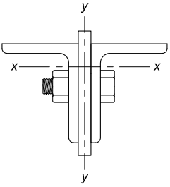
Figure description:
Entities & Key Information:
- Subject: Built-up double-angle compression member cross-section (Fig. C-E6.1.
- Components:
- Two structural steel angles positioned back-to-back.
- Central separator/filler plate between the angles.
- Bolted connection consisting of a bolt head, shank, and nut securing the assembly.
- Reference Axes:
- axis: Horizontal centroidal axis.
- axis: Vertical axis of symmetry passing through the center of the filler plate.
- Context: Structural engineering detail for built-up member design, specifically addressing connector spacing and end connections.
Fig. C-E6.1. Built-up double-angle compression member.
where the individual components are widely spaced are also provided. Some dimensioning requirements are based upon judgment and experience. The provisions governing the proportioning of perforated cover plates are based upon extensive experimental research (Stang and Jaffe, 1948).