C-FCommentary — Chapter F Design of members for flexure
PDF page 438 · AISC 360-22
Chapter F includes the following major changes and additions in this edition of the Specification:
- (1) Strength equations for HSS and box sections have been reformatted and a restriction provided for box sections with slender webs and slender flanges.
- (2) Provisions for rectangular bars and rounds have been simplified although no changes in resulting strength have been made.
- (3) For flexural strength of members with holes in the tension flange it has been clarified that these provisions apply only to bolt holes.
- (4) Requirements for unbraced length with moment redistribution have been moved to Appendix 8.
Chapter F applies to members subjected to simple bending about one principal axis of the cross section. That is, the member is loaded in a plane parallel to a principal axis that passes through the shear center. Simple bending may also be attained if all load points and supports are restrained against twisting about the longitudinal axis. In all cases, the provisions of this chapter are based on the assumption that points of support for all members are restrained against rotation about their longitudinal axis. Because the strength equations presented in this chapter are based on theory and testing, they are based in part on the tolerances provided in the applicable material standards. If those tolerances are exceeded, appropriate reductions in strength may be needed.
Section F2 gives the provisions for the flexural strength of doubly symmetric compact I-shaped and channel members subjected to bending about their major axis. For most designers, the provisions in this section will be sufficient to perform their everyday designs. The remaining sections of Chapter F address less frequently occurring cases encountered by structural engineers. Because there are many such cases, many equations and many pages in the Specification, the table in User Note F1.1 is provided as a map for navigating through the cases considered in Chapter F. The coverage of the chapter is extensive and there are many equations that appear formidable; however, it is stressed again that for most designs, the engineer need seldom go beyond Section F2. AISC Design Guide 25, Frame Design Using Nonprismatic Members (White et al., 2021), addresses flexural strength for web-tapered members.
For all cross sections covered in Chapter F, the highest possible nominal flexural strength is the plastic moment, . Being able to use this value in design represents the optimum use of the steel. In order to attain , the beam cross section must be compact and the member must have sufficient lateral bracing.
Compactness depends on the flange and web width-to-thickness ratios, as defined in Section B4. When these conditions are not met, the nominal flexural strength diminishes. All sections in Chapter F treat this reduction in the same way. For beams with full lateral bracing, the plastic moment region extends over the range of width-to-thickness ratios, , terminating
at . This is the compact condition. Beyond these limits, the nominal flexural strength reduces linearly until reaches . This is the range where the cross section is noncompact. Beyond the cross section is a slender-element section. These three ranges are illustrated in Figure C-F1.1 for the case of rolled wide-flange members for the limit state of flange local buckling. The curve in Figure C-F1.1 shows the relationship between the flange width-to-thickness ratio, , and the nominal flexural strength, .
The basic relationship between the nominal flexural strength, , and the unbraced length, , for the limit state of lateral-torsional buckling is shown by the solid curve in Figure C-F1.2 for a compact section that is simply supported and subjected to uniform bending with .
For the case of rolled wide-flange members, there are three principal zones defined on the basic curve by the lengths and . Equation F2-5 defines the maximum unbraced length, , to reach with uniform moment. Elastic lateral-torsional buckling will occur when the unbraced length is greater than , given by Equation F2-6. Equation F2-2 defines the range of inelastic lateral-torsional buckling as a straight line between the defined limits at and at . Buckling strength in the elastic region is given by Equation F2-3 in combination with Equation F2-4.
For other than uniform moment along the member length, the lateral buckling strength is obtained by multiplying the basic strength in the elastic and inelastic region by as shown in Figure C-F1.2. However, in no case can the maximum nominal flexural strength exceed the plastic moment, . Note that given by Equation F2-5 has physical meaning only for . For greater than 1.0, members with larger unbraced lengths can reach , as shown by the dashed curve for in Figure C-F1.2. The largest length at which is calculated by setting Equation F2-2 equal to and solving for using the actual value of .
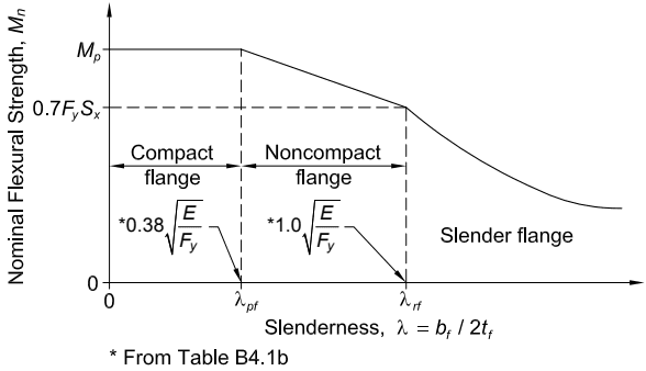
Figure description:
Structural Steel Design: Flange Local Buckling Effect of Flange Slenderness on Flexural Capacity
Nominal Flexural Strength, vs. Slenderness,
Annotations
- Compact flange (text_label - position: Horizontal region from λ = 0 to λ_pf)
- Noncompact flange (text_label - position: Sloped region from λ_pf to λ_rf)
- Slender flange (text_label - position: Curved region where λ > λ_rf)
- *0.38 sqrt(E/F_y (vertical_line - position: x = λ_pf))
- *1.0 sqrt(E/F_y (vertical_line - position: x = λ_rf))
- M_p (text_label - position: y-intercept and plateau height)
- 0.7 F_y S_x (text_label - position: y-value at λ = λ_rf)
| Slenderness () | Nominal Flexural Strength () | Flange Classification |
|---|---|---|
| 0 | Compact flange | |
| Compact flange boundary | ||
| ) | Noncompact flange (Linear transition) | |
| Noncompact flange boundary | ||
| Decreasing (Elastic Buckling) | Slender flange |
Source: AISC Table B4.1b Notes: The chart illustrates the nominal flexural strength of a beam as a function of flange slenderness (λ = b_f / 2t_f. The behavior transitions from plastic capacity (M_p for compact flanges, through a linear reduction for noncompact flanges, to a non-linear (likely elastic buckling curve for slender flanges. Values for λ boundaries are derived from AISC Table B4.1b.)))
Fig. C-F1.1. Nominal flexural strength as a function of the flange width-to-thickness ratio of rolled I-shapes.
- F1 GENERAL PROVISIONS
- F2 DOUBLY SYMMETRIC COMPACT I-SHAPED MEMBERS AND CHANNELS BENT ABOUT THEIR MAJOR AXIS
- F3 DOUBLY SYMMETRIC I-SHAPED MEMBERS WITH COMPACT WEBS AND NONCOMPACT OR SLENDER FLANGES BENT ABOUT THEIR MAJOR AXIS
- F4 OTHER I-SHAPED MEMBERS WITH COMPACT OR NONCOMPACT WEBS BENT ABOUT THEIR MAJOR AXIS
- F5 DOUBLY SYMMETRIC AND SINGLY SYMMETRIC I-SHAPED MEMBERS WITH SLENDER WEBS BENT ABOUT THEIR MAJOR AXIS
- F6 I-SHAPED MEMBERS AND CHANNELS BENT ABOUT THEIR MINOR AXIS
- F7 SQUARE AND RECTANGULAR HSS AND BOX SECTIONS
- F8 ROUND HSS
- F9 TEES AND DOUBLE ANGLES LOADED IN THE PLANE OF SYMMETRY
- F10 SINGLE ANGLES
- F11 RECTANGULAR BARS AND ROUNDS
- F12 UNSYMMETRICAL SHAPES
- F13 PROPORTIONS OF BEAMS AND GIRDERS