C-F10F10 Single angles
PDF page 456 · AISC 360-22
Flexural strength limits are established for the limit states of yielding, lateral-torsional buckling, and leg local buckling of single-angle beams. In addition to addressing the general case of unequal-leg single angles, the equal-leg angle is treated as a special case. Furthermore, bending of equal-leg angles about a geometric axis, an axis parallel to one of the legs, is addressed separately as it is a common case of angle bending.
The tips of an angle refer to the free edges of the two legs. In most cases of unrestrained bending, the flexural stresses at the two tips will have the same sign (tension or compression). For constrained bending about a geometric axis, the tip stresses will differ in sign. Provisions for both tension and compression at the tip should be checked, as appropriate, but in most cases it will be evident which controls.
Appropriate serviceability limits for single-angle beams need to also be considered. In particular, for longer members subjected to unrestrained bending, deflections are likely to control rather than lateral-torsional buckling or leg local buckling strength.
The provisions in this section follow the general format for nominal flexural resistance (see Figure C-F1.2). There is a region of full plastification, a linear transition to the yield moment, and a region of local buckling.
F10.1 Yielding
The strength at full yielding is limited to 1.5 times the yield moment. This limit acts as a limit on the ratio of plastic moment to yield moment, , which can also be represented as . This ratio is also known as the shape factor. The limit in Equation F10-1 assures an upper-bound plastic moment for an angle that could be bent about any axis, in as much as these provisions are applicable to all flexural conditions. A 1.25 factor had been used in the past and was known to be a conservative value. Research (Earls and Galambos, 1997) has indicated that the 1.5 factor represents a better upper-bound value. Because the shape factor for angles is in excess of 1.5 , the nominal strength, , for compact members is justified provided that instability does not control.
F10.2 Lateral-Torsional Buckling
Lateral-torsional buckling may limit the flexural strength of an unbraced singleangle beam. As illustrated in Figure C-F10.1, Equation F10-3 represents the elastic buckling portion with the maximum nominal flexural strength, , equal to of the theoretical buckling moment, . Equation F10-2 represents the inelastic buckling transition expression between and . The maximum beam flexural strength, , will occur when the theoretical buckling moment, , reaches or exceeds is the moment at first yield in Equations F10-2 and F10-3, the same as the in Equation F10-1. These equations are modifications of those developed from the results of Australian research on single angles in flexure and on an analytical model consisting of two rectangular elements of length equal to the actual angle leg width minus one-half the thickness (AISC, 1975; Leigh and Lay, 1978, 1984; Madugula and Kennedy, 1985).
When bending is applied about one leg of a laterally unrestrained single angle, the angle will deflect laterally as well as in the bending direction. Its behavior can be evaluated by resolving the load and/or moments into principal axis components and determining the sum of these principal axis flexural effects. Subsection (i) of Section F10.2(2) is provided to simplify and expedite the calculations for this common situation with equal-leg angles. For such unrestrained bending of an equal-leg angle, the resulting maximum normal stress at the angle tip (in the direction of bending) will be approximately greater than the calculated stress using the geometric axis section modulus. The value of given by Equations F10-5a and F10-5b and the evaluation of using 0.80 of the geometric axis section modulus reflect bending about the inclined axis shown in Figure C-F10.2. Dumonteil (2009) compares the results using the geometric axis approach with that of the principal-axis approach for lateral-torsional buckling.
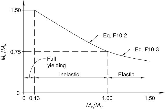
Figure description:
Flexural Strength Design Curve
Normalized Nominal Moment Capacity (Mn/My vs. Relative Slenderness (My/Mcr
Legend
- Eq. F10-2 — color: black; symbol: Solid line
- Eq. F10-3 — color: black; symbol: Solid line
- Full yielding — color: black; symbol: Solid line
Annotations
- Full yielding (text_label - position: 0.00 < My/Mcr < 0.13)
- Inelastic (text_label - position: 0.13 < My/Mcr < 1.00)
- Elastic (text_label - position: My/Mcr > 1.00)
- Transition at 0.13 (vertical_line - position: x = 0.13)
- Transition at 1.00 (vertical_line - position: x = 1.00)
- Horizontal limit at 0.75 (horizontal_line - position: y = 0.75)
| My / Mcr | Mn / My | Region / Equation |
|---|---|---|
| 0.00 | 1.50 | Full yielding |
| 0.13 | 1.50 | Full yielding |
| 0.13 | 1.50 | Eq. F10-2 |
| 1.00 | 0.75 | Eq. F10-2 |
| 1.00 | 0.75 | Eq. F10-3 |
| 1.50 | 0.60 | Eq. F10-3 |
Notes: The chart illustrates three behavioral regions for flexural strength: full yielding (constant at 1.50, inelastic buckling (linear transition from 1.50 to 0.75, and elastic buckling (curved decay. The x-axis represents the ratio of yield moment to critical elastic moment, while the y-axis represents the nominal moment capacity normalized by the yield moment. The data point at My/Mcr = 1.50 is a visual estimate.)))
Fig. C-F10.1. Lateral-torsional buckling limits of a single-angle beam.
The deflection calculated using the geometric axis moment of inertia has to be increased 82% to approximate the total deflection. Deflection has two components: a vertical component (in the direction of applied load) of 1.56 times the calculated value, and a horizontal component of 0.94 times the calculated value. The resultant total deflection is in the general direction of the minor principal axis bending of the angle (see Figure C-F10.2). These unrestrained bending deflections should be considered in evaluating serviceability and will often control the design over lateral- torsional buckling.
The horizontal component of deflection being approximately 60% of the vertical deflection means that the lateral restraining force required to achieve purely vertical deflection must be 60% of the applied load value (or produce a moment 60% of the applied value), which is very significant.
Lateral-torsional buckling is limited by (Leigh and Lay, 1978, 1984) as defined in Equation F10-5a, which is based on
(the general expression for the critical moment of an equal-leg angle) with for the condition where the angle tip stress is compressive (see Figure C-F10.3). Lateral-torsional buckling can also limit the flexural strength of the cross section when the maximum angle tip stress is tensile from geometric axis flexure, especially with use of the flexural strength limits in Section F10.2. Using in Equation C-F10-1, the resulting expression is Equation F10-5b with a +1 instead of -1 as the last term.
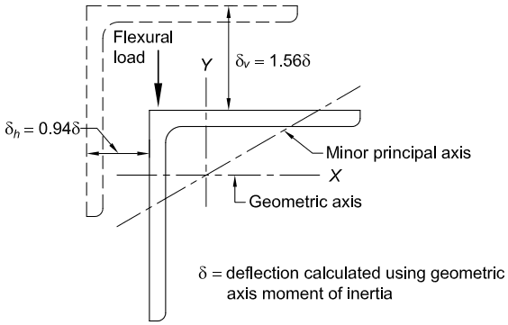
Figure description:
Subject: Deflection for geometric axis bending of laterally unrestrained equal-leg angles (Fig. C-F10.2.
Key Entities and Information:
- Equal-Leg Angle: Shown in cross-section with geometric axes ( and a minor principal axis.
- Flexural Load: Vertical force applied at the heel/tip junction.
- Deflection Components:
- Vertical Deflection (:
- Horizontal Deflection (:
- Reference Variable (: Deflection calculated using the geometric axis moment of inertia.
- Visual Representation: Dashed lines indicate the original position, showing both vertical and lateral displacement under load.
Fig. C-F10.2. Deflection for geometric axis bending of laterally unrestrained equal-leg angles.
Stress at the tip of the angle leg parallel to the applied bending axis is of the same sign as the maximum stress at the tip of the other leg when the single angle is unrestrained. For an equal-leg angle this stress is about one-third of the maximum stress. It is only necessary to check the nominal bending strength based on the tip of the angle leg with the maximum stress when evaluating such an angle. If an angle is subjected to an axial compressive load, the flexural limits obtained from Section F10.2, item (2), cannot be used due to the inability to calculate a proper moment magnification factor for use in the interaction equations.
For unequal-leg angles and for equal-leg angles in compression without lateral-torsional restraint, the applied load or moment must be resolved into components along the two principal axes in all cases and design must be for biaxial bending using the interaction equations in Chapter H.
Under major-axis bending of single angles, Equation F10-4 in combination with Equations F10-2 and F10-3 control the available moment against overall lateral-torsional buckling of the angle. This is based on given in Equation C-F10-1 with .
Lateral-torsional buckling will reduce the stress below only for . For an equal-leg angle bent about its major principal axis, this occurs for . If the parameter is small (less than approximately for this case), local buckling will control the available moment and based on lateral-torsional buckling need not be evaluated. Local buckling must be checked using Section F10.3.
Lateral-torsional buckling about the major principal axis ( -axis) of an angle is controlled by in Equation F10-4. The section property, , which is nonzero for unequal-leg angles reflects the location of the shear center relative to the principal axis of the section and the bending direction under uniform bending. Positive and
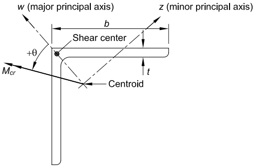
Figure description:
Key Information:
- Subject: Structural equal-leg angle section.
- Geometric Parameters:
- : Leg width.
- : Leg thickness.
- Principal Axes:
- : Major principal axis.
- : Minor principal axis.
- Key Points:
- Shear center: Located at the intersection of the leg centerlines.
- Centroid: Located within the interior area of the angle.
- Loading Parameters:
- : Vector representing the critical moment.
- : Angle of the moment vector relative to the major principal axis (.
Fig. C-F10.3. Equal-leg angle with general moment loading.
maximum Mcr occur when the shear center is in flexural compression while negative βw and minimum Mcr occur when the shear center is in flexural tension (see Figure C-F10.4). This βw effect is consistent with the behavior of singly symmetric I-shaped beams, which are more stable when the compression flange is larger than the tension flange.
For reverse curvature bending, part of the unbraced length has positive , while the remainder has negative ; conservatively, the negative value is assigned for that entire unbraced segment.
The factor is essentially independent of angle thickness (less than 1% variation from mean value) and is primarily a function of the leg widths. The average values shown in Table C-F10.1 may be used for design.
F10.3 Leg Local Buckling
The limits were modified for the 2010 AISC Specification to be more representative of flexural limits rather than using those for single angles under uniform compression. Typically, the flexural stresses will vary along the leg length permitting the use of the stress limits given. Even for the geometric axis flexure case, which produces uniform compression along one leg, use of these limits will provide a conservative value when compared to the results reported in Earls and Galambos (1997).