C-F11F11 Rectangular bars and rounds
PDF page 460 · AISC 360-22
The provisions in Section F11 apply to solid bars with round and rectangular cross section. The prevalent limit state for such members is the attainment of the full plastic moment, . The exception is the lateral-torsional buckling of rectangular bars where the depth is larger than the width. The requirements for design are identical to those given in Table A-F1.1 in the 1999 LRFD Specification (AISC, 2000b) and the same as those in use since the 2005 AISC Specification (AISC, 2005b). Because the shape factor, , for a rectangular cross section is 1.5 and for a round section is 1.7 , consideration must be given to serviceability issues such as excessive deflection or permanent deformation under service-load conditions.
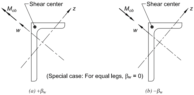
Figure description:
Figure Description: Unequal-leg angle in bending
- Principal Axes: Labeled as and .
- Loading: Bending moment applied along the -axis.
- Configurations:
- (a : Moment vector directed away from the angle cross-section.
- (b : Moment vector directed toward the angle cross-section.
- Shear Center: Identified at the junction of the two legs.
- Note: For equal-leg angles, the value of is zero.
Fig. C-F10.4. Unequal-leg angle in bending.
Specification for Structural Steel Buildings, August 1, 2022 AMERICAN INSTITUTE OF STEEL CONSTRUCTION
TABLE C-F10.1
βw Values for Angles
| Angle size, in. (mm) | βw, in. (mm)[a] |
|---|---|
| 8 × 6 (203 × 152) | 3.31 (84.1) |
| 8 × 4 (203 × 102) | 5.48 (139) |
| 7 × 4 (178 × 102) | 4.37 (111) |
| 6 × 4 (152 × 102) | 3.14 (79.8) |
| 6 × 3½ (152 × 89) | 3.69 (93.7) |
| 5 × 3½ (127 × 89) | 2.40 (61.0) |
| 5 × 3 (127 × 76) | 2.99 (75.9) |
| 4 × 3½ (102 × 89) | 0.87 (22.1) |
| 4 × 3 (102 × 76) | 1.65 (41.9) |
| 3½ × 3 (89 × 76) | 0.87 (22.1) |
| 3½ × 2½ (89 × 64) | 1.62 (41.1) |
| 3 × 2½ (76 × 64) | 0.86 (21.8) |
| 3 × 2 (76 × 51) | 1.56 (39.6) |
| 2½ × 2 (64 × 51) | 0.85 (21.6) |
| 2½ × 1½ (64 × 38) | 1.49 (37.8) |
| Equal legs | 0.00 |
where
moment of inertia for the major principal axis, in.
has a positive or negative value depending on the direction of bending (see Figure C-F10.4).