C-F7F7 Square and rectangular HSS and box sections
PDF page 449 · AISC 360-22
The provisions for the nominal flexural strength of HSS and box sections include the limit states of yielding, flange local buckling, web local buckling, and lateral-torsional buckling.
The provisions for local buckling of noncompact rectangular HSS are the same as those in the previous sections of this chapter: for , and a linear transition from to when . Equations F7-2 and F7-6 have been restructured to conform to similar equations for sections with noncompact elements in Chapter F and to include both HSS and box sections. The equation for the
effective width of the compression flange when exceeds is the same as that used for rectangular HSS in axial compression in the 2010 AISC Specification (AISC, 2010), except that the stress is taken as the yield stress. This implies that the stress in the corners of the compression flange is at yield when the ultimate post-buckling strength of the flange is reached. When using the effective width, the nominal flexural strength is determined from the effective section modulus referred to the compression flange using the distance from the shifted neutral axis. A slightly conservative estimate of the nominal flexural strength can be obtained by using the effective width for both the compression and tension flange, thereby maintaining the symmetry of the cross section and simplifying the calculations. For box sections, is the same as that used for uniformly compressed slender elements under compression in the 2010 AISC Specification.
Although there are no HSS with slender webs in flexural compression, Section F7.3(c) is included to account for box sections that may have slender webs. The provisions of Section F5 for I-shaped members have been adopted with a doubling of aw to account for two webs. Sections with slender webs and slender flanges are not considered in this Specification because their behavior is difficult to predict; such members should be used with care.
Because of the high torsional resistance of the closed cross section, the critical unbraced lengths, and , that correspond to the development of the plastic moment and the yield moment, respectively, are typically relatively large. For example, as shown in Figure C-F7.1, an HSS20x4x5/16 (HSS508x101.6x7.9), which has one of the largest depth-to-width ratios among standard HSS, has of 6.7 ft (2.0 m) and of 137 ft (42 m). An extreme deflection limit might correspond to a
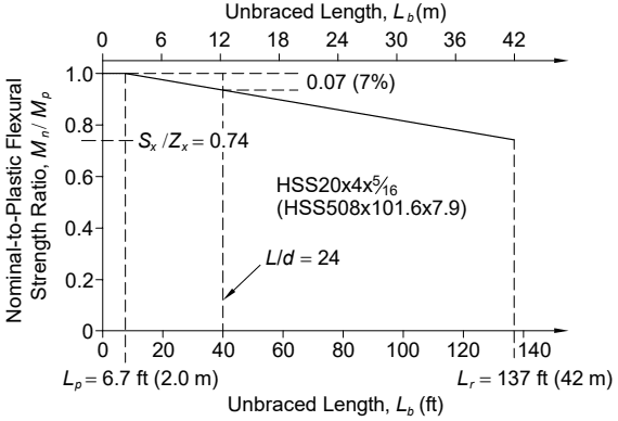
Figure description:
Flexural Strength Reduction with Unbraced Length HSS20x4x5/16 (HSS508x101.6x7.9
Nominal-to-Plastic Flexural Strength Ratio vs. Unbraced Length
Annotations
- L_p = 6.7 ft (2.0 m (vertical_line - position: x = 6.7 ft))
- L/d = 24 (vertical_line - position: x = 40 ft)
- L_r = 137 ft (42 m (vertical_line - position: x = 137 ft))
- S_x / Z_x = 0.74 (text_label - position: y = 0.74)
- 0.07 (7% (text_label - position: y difference at L_b = 40 ft))
- HSS20x4x5/16 (HSS508x101.6x7.9 (text_label - position: center))
| Unbraced Length, (ft) | Unbraced Length, (m) | Nominal-to-Plastic Flexural Strength Ratio, |
|---|---|---|
| 0 | 0 | 1.0 |
| 6.7 () | 2.0 | 1.0 |
| 40.0 () | 12.2 | 0.93 |
| 137.0 () | 42.0 | 0.74 |
Notes: The chart illustrates the flexural strength behavior for an HSS section. It shows a constant full plastic strength ratio of 1.0 up to the plastic limit length L_p, followed by a linear reduction due to lateral-torsional buckling as the unbraced length increases towards L_r. At L_b = 40 ft, the strength is reduced by 7% (0.07. The terminal strength ratio at L_r corresponds to the elastic section modulus ratio S_x/Z_x = 0.74.)
Fig. C-F7.1. Lateral-torsional buckling of rectangular HSS .
length-to-depth ratio of 24 or a length of 40 ft (12 m) for this member. Using the specified linear reduction between the plastic moment and the yield moment for lateral-torsional buckling, the plastic moment is reduced by only 7% for the 40 ft (12 m) length. In most practical designs with HSS where there is a moment gradient and the lateral-torsional buckling modification factor, , is larger than unity, the reduction will be nonexistent or insignificant.
Section F7.4 is included to account for the lateral-torsional buckling of very narrow box sections and box sections with plates thinner than HSS with the largest depth-to-width ratio. The provisions are from the 1989 AISC Specification (AISC, 1989), which were removed in subsequent editions where only HSS were addressed.