C-F1F1 General provisions
PDF page 440 · AISC 360-22
Throughout Chapter F, the resistance factor and the safety factor remain unchanged, regardless of the controlling limit state. This includes the limit state defined in Section F13 for design of flexural members with bolt holes in the tension flange where rupture is the controlling limit state (Geschwindner, 2010a).
In addition, the requirement that all supports for flexural members be restrained against rotation about the longitudinal axis is stipulated. Although there are provi- sions for members unbraced along their length, under no circumstances can the supports remain unrestrained torsionally.
Beginning with the 1961 AISC Specification (AISC, 1961) and continuing through the 1986 LRFD Specification (AISC, 1986), the following equation was used to adjust the lateral-torsional buckling equations for variations in the moment diagram within the unbraced length:
(C-F1-1)
where
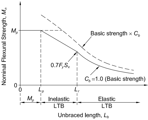
Figure description:
Nominal Flexural Strength, as a function of Unbraced Length,
Nominal Flexural Strength vs. Unbraced Length
Legend
- (Basic strength — color: black; symbol: Solid line
- Basic strength — color: black; symbol: Dashed line
Annotations
- (Plastic Region (region - position: 0 <= <= ))
- Inelastic LTB (region - position: < <= )
- Elastic LTB (region - position: > )
- (text_label - position: Point on solid curve at )
- (text_label - position: y-axis value for plateau)
| Unbraced length () | Nominal Flexural Strength () [Basic strength, | Nominal Flexural Strength () [Basic strength |
|---|---|---|
| Between and | Inelastic Lateral-Torsional Buckling (LTB region: linear transition from to ) | Plateaus at until Basic Strength , then Inelastic LTB |
| (capped at ) | ||
| Beyond | Elastic Lateral-Torsional Buckling (LTB region: asymptotic decrease towards zero) | Elastic LTB (capped at ) |
Notes: The graph depicts the three behavioral states of a beam's flexural capacity based on its unbraced length : Plastic (up to , Inelastic Lateral-Torsional Buckling (between and , and Elastic Lateral-Torsional Buckling (beyond . The factor accounts for the moment gradient; while it can increase the nominal strength, the resulting is capped at the plastic moment capacity .)))
Fig. C-F1.2. Nominal flexural strength as a function of unbraced length and moment gradient.
This equation is applicable strictly only to moment diagrams that consist of straight lines between braced points—a condition that is rare in beam design. The equation provides a lower bound to the solutions developed in Salvadori (1956). Equation C-F1-1 can be applied to nonlinear moment diagrams by using a straight line between and the moment at the middle of the unbraced length and taking as the value on this straight line at the opposite end of the unbraced length (AASHTO, 2014). If the moment at the middle of the unbraced length is greater than is conservatively taken equal to 1.0 when applying Equation C-F1-1 in this manner.
Kirby and Nethercot (1979) present an equation that is a direct fit to various non-linear moment diagrams within the unbraced segment. Their original equation was slightly adjusted to give Equation C-F1-2a (Equation F1-1 in this Specification):
(C-F1-2a)
This equation gives a more accurate solution for unbraced lengths in which the moment diagram deviates substantially from a straight line, such as the case of a fixed-end beam with no lateral bracing within the span, subjected to a uniformly distributed transverse load. It gives slightly conservative results compared to Equation C-F1-1, in most cases, for moment diagrams with straight lines between points of bracing. The absolute values of the three quarter-point moments and the maximum moment, regardless of its location, are used in Equation C-F1-2a. Wong and Driver (2010) review a number of approaches and recommend the following alternative quarter-point equation for use with doubly symmetric I-shaped members:
(C-F1-2b)
This equation gives improved predictions for a number of important cases, including cases with moderately nonlinear moment diagrams. The maximum moment in the unbraced segment is used in all cases for comparison with the nominal moment, . In addition, the length between braces, not the distance to inflection points, is used in all cases.
The lateral-torsional buckling modification factor given by Equation C-F1-2a is applicable for doubly symmetric sections and singly symmetric sections in single curvature. It should be modified for application with singly symmetric sections in reverse curvature. Previous work considered the behavior of singly symmetric I-shaped beams subjected to gravity loading (Helwig et al., 1997). The study resulted in the following expression:
(C-F1-3)
For single curvature bending
For reverse curvature bending
(C-F1-4)
where
Equation C-F1-3 was developed for gravity loading on beams with a horizontal orientation of the longitudinal axis. For more general cases, the top flange is defined as the flange on the opposite side of the web mid-depth from the direction of the transverse loading. The term in parentheses in Equation C-F1-3 is identical to Equation C-F1-2a, while the factor is a modifier for singly symmetric sections that is greater than unity when the top flange is the larger flange and less than unity when the top flange is the smaller flange. For singly symmetric sections subjected to reverse curvature bending, the lateral-torsional buckling strength should be evaluated by separately treating each flange as the compression flange and comparing the available flexural strength with the required moment that causes compression in the flange under consideration.
The factors discussed in the foregoing are defined as a function of the spacing between braced points. However, many situations arise where a beam may be subjected to reverse curvature bending and have one of the flanges continuously braced laterally by closely spaced joists and/or light gage decking normally used for roofing or flooring systems. Although the lateral bracing provides significant restraint to one of the flanges, the other flange can still buckle laterally due to the compression caused by the reverse curvature bending. A variety of expressions have been developed that are a function of the type of loading, distribution of the moment, and the support conditions. For gravity loaded rolled I-section beams with the top flange laterally restrained, the following expression is applicable (Yura, 1995; Yura and Helwig, 2010):
(C-F1-5)
where
The unbraced length is defined as the spacing between locations where twist is restrained. The sign convention for the moments is shown in Figure C-F1.3. , and are all taken as positive when they cause compression on the top flange, and they are taken as negative when they cause compression on the bottom flange, as shown in the figure. The asterisk on the last term in Equation C-F1-5 indicates
that is taken as zero in the last term if it is positive. For example, considering the distribution of moment shown in Figure C-F1.4, the value would be
Note that is taken as because is positive.
In this case, would be used with the lateral-torsional buckling strength for the beam using an unbraced length of 20 ft (6.1 m), which is defined by the locations where twist or lateral movement of both flanges is restrained.
A similar buckling problem occurs with rolled I-shaped roofing beams subjected to uplift from wind loading. The light gage metal decking that is used for the roofing system usually provides continuous restraint to the top flange of the beam; however, the uplift can be large enough to cause the bottom flange to be in compression. The sign convention for the moment is the same as indicated in Figure C-F1.3. The moment must cause compression in the bottom flange ( negative) for the beam to buckle. Three different expressions are given in Figure C-F1.5 depending on whether the end moments are positive or negative (Yura and Helwig, 2010). As outlined in
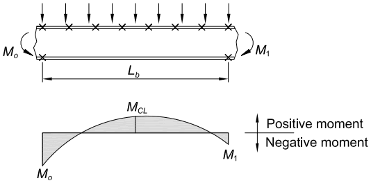
Figure description:
Structural Beam Loading and Bending Moment Diagram
Bending Moment Diagram for a Loaded Beam Segment
Legend
- Positive moment — symbol: Upward arrow
- Negative moment — symbol: Downward arrow
Annotations
- (Span Length (text_label - position: Horizontal distance between end points))
- Centerline (vertical_line - position: Midpoint of span )
- Distributed Load (text_label - position: Vertical arrows along the top of the beam)
- End Moments () and (text_label - position: Ends of the beam segment)
| Location | Moment Magnitude | Moment Type |
|---|---|---|
| Left End (0) | Negative | |
| Midspan () | Positive | |
| Right End () | Negative |
Notes: The diagram illustrates the sign convention for bending moments where positive moments are plotted above the axis and negative moments below. The beam is subjected to a distributed load and end moments and .
Fig. C-F1.3. Sign convention for moments in Equation C-F1-5.
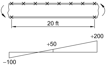
Figure description:
Beam Loading and Distribution Diagram
Linear Distribution along a 20 ft Beam
Annotations
- -100 (text_label - position: Left end of the distribution graph at 0 ft)
- +50 (text_label - position: Midpoint of the distribution graph at 10 ft)
- +200 (text_label - position: Right end of the distribution graph at 20 ft)
- 20 ft (dimension_line - position: Horizontal distance between the end markers on the beam)
| Distance along beam (ft) | Distribution Value |
|---|---|
| 0 | -100 |
| 10 | 50 |
| 20 | 200 |
Notes: The figure consists of two parts: a diagram of a beam and a corresponding distribution graph below it. The beam diagram shows a 20 ft section marked with 'x' symbols (8 along the top edge and 2 at the bottom corners and curved arrows at both ends indicating applied moments. The distribution graph shows a linear variation from -100 at the left end to +200 at the right end, crossing through +50 at the exact center of the 20 ft span.)
Fig. C-F1.4. Moment diagram for numerical example of application of Equation C-F1-5.
the foregoing, the unbraced length is defined as the spacing between points where both the top and bottom flange are restrained from lateral movement or between points restrained from twist.
The equations for the limit state of lateral-torsional buckling in Chapter F assume that the loads are applied along the beam centroidal axis. may be conservatively taken equal to 1.0 , with the exception of some cases involving unbraced overhangs or members with no bracing within the span and with significant loading applied to the top flange. If the load is placed on the top flange and the flange is not braced, there is a tipping effect that reduces the critical moment; conversely, if the load is suspended from an unbraced bottom flange, there is a stabilizing effect that increases the critical moment (Ziemian, 2010). For unbraced top flange loading on compact I -shaped members, the reduced critical moment may be conservatively approximated by setting the square root expression in Equation F2-4 equal to unity.
An effective length factor of unity is implied in the critical moment equations to represent the worst-case simply supported unbraced segment. Consideration of any end restraint due to adjacent unbuckled segments on the critical segment can increase its strength. The effects of beam continuity on lateral-torsional buckling have been studied, and a simple conservative design method based on the analogy to end-restrained nonsway columns with an effective length less than unity is proposed in Ziemian (2010).
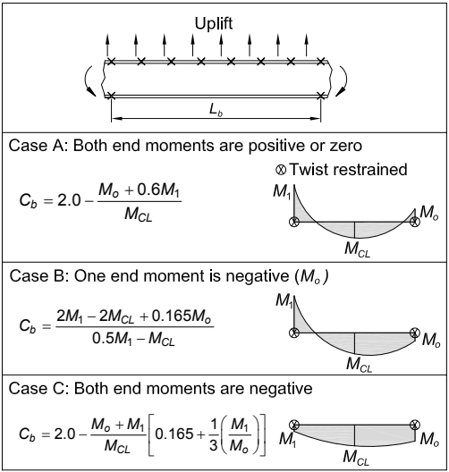
Figure description:
Image Overview: The figure illustrates (lateral-torsional buckling modification factors for uplift loading on rolled I-shaped beams with the top flange continuously restrained laterally.
Key Entities & Information:
- Loading: Uplift (upward arrows acting on a beam segment of length .
- Restraint: Top flange is continuously restrained; "" symbols denote twist restraint at the segment ends.
- Parameters:
- : Moment at the left end.
- : Moment at the right end.
- : Moment at the centerline of the segment.
Case Classifications and Formulas:
| Case | Condition | Formula |
|---|---|---|
| Case A | Both end moments are positive or zero | |
| Case B | One end moment is negative () | |
| Case C | Both end moments are negative | ) |
Fig. C-F1.5. Cb factors for uplift loading on rolled I-shaped beams with the top flange continuously restrained laterally.