C-F4F4 Other I-shaped members with compact or noncompact webs bent about their major axis
PDF page 447 · AISC 360-22
The provisions of Section F4 are applicable to doubly symmetric I-shaped beams with noncompact webs and to singly symmetric I-shaped members with compact or noncompact webs (see the table in User Note F1.1). This section addresses welded I-shaped beams where the webs are not slender. The flanges may be compact, non-compact, or slender. The contents of Section F4 are based on White (2008).
Four limit states are considered in Section F4: (a) compression flange yielding; (b) lateral-torsional buckling; (c) compression flange local buckling; and (d) tension flange yielding. The effect of inelastic local buckling of the web is addressed indirectly by multiplying the moment causing yielding in the compression flange by a factor, , and the moment causing yielding in the tension flange by a factor, . These two factors can vary from unity to as high as and . The maximum limit of 1.6 is intended to guard against substantial early yielding potentially leading to inelastic response under service conditions. They can be assumed to conservatively equal 1.0 although in many circumstances this will be much too conservative to be a reasonable assumption. The following steps are provided as a guide to the determination of and .
Step 1. Calculate and , as defined in Figure C-F4.1.
Step 2. Determine the web slenderness and the yield moments in compression and tension:
(C-F4-1)
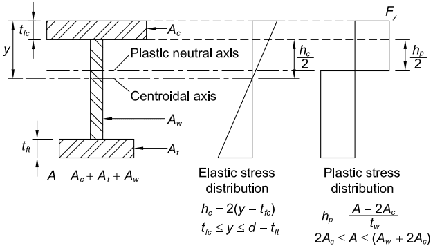
Figure description:
Key Information Extraction: Elastic and Plastic Stress Distributions (Fig. C-F4.1
Structural Components
- / : Compression flange area and thickness.
- / : Tension flange area and thickness.
- : Web area.
- : Total cross-sectional area (.
Reference Axes
- Centroidal Axis: The neutral axis for elastic stress distribution where stress is zero.
- Plastic Neutral Axis: The axis where plastic stress changes from compression to tension.
Stress Distributions
- Elastic Stress Distribution: Linear variation across the depth.
- Defined by height .
- Applicable range: .
- Plastic Stress Distribution: Constant stress ( throughout the section, reversing sign at the plastic neutral axis.
- Defined by height .
- Valid when .
Fig. C-F4.1. Elastic and plastic stress distributions.
Step 3. Determine and
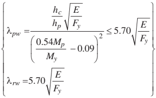
Figure description:
Mathematical equations for web slenderness limits (C-F4-2:
- Compact web limit (:
- Noncompact web limit (:
Key Variables:
- : Slenderness limits
- : Web depth parameters
- : Modulus of elasticity
- : Specified minimum yield stress
- : Plastic and yield moments
(C-F4-2)
If , then the web is slender and the design is governed by Section F5. In extreme cases where the plastic neutral axis is located in the compression flange, and the web is considered to be compact.
Step 4. Calculate and using Section F4.
The basic maximum nominal moment is corresponding to the compression flange, and corresponding to tension flange yielding, which is applicable only when or (beams with the larger flange in compression). The Section F4 provisions parallel the rules for doubly symmetric members in Sections F2 and F3. Equations F2-4 and F2-6 are nearly the same as Equations F4-5 and F4-8, with the former using and the latter using , both representing the elastic section modulus to the compression side. This is a simplification that tends to be somewhat conservative if the compression flange is smaller than the tension flange, and it is somewhat unconservative when the reverse is true (White and Jung, 2003). It is required to check for tension flange yielding if the tension flange is smaller than the compression flange (Section F4.4).
For a more accurate solution, especially when the loads are not applied at the centroid of the member, the designer is directed to Galambos (2001), White and Jung (2003), and Ziemian (2010). The following alternative equations in lieu of Equations F4-5 and F4-8 are provided by White and Jung:
(C-F4-3)
(C-F4-4)
where the coefficient of monosymmetry, , the warping constant, , where , and is the magnitude of the flexural stress in compression at which the lateral-torsional buckling is influenced by yielding. In Equations F4-6a and F4-6b, this stress level is taken generally as the smaller of in the compression flange, or the compression flange stress when the tension flange reaches the yield strength, but not less than .