C-I1I1 General provisions
PDF page 486 · AISC 360-22
Design of composite members requires consideration of structural steel, reinforcing steel, and concrete behavior. These provisions were developed with the intent both to minimize conflicts between current steel and reinforced concrete design and detailing provisions and to give proper recognition to the advantages of composite design.
The provisions in Chapter I address strength design of composite members only. The designer needs to consider the loads resisted by the steel section alone when determining load effects during the construction phase. The designer also needs to consider deformations throughout the life of the structure and the appropriate cross section for those deformations. When considering these latter limit states, due allowance should be made for the additional long-term changes in stresses and deformations due to creep and shrinkage of the concrete.
Reference is made to ACI 318 and ACI 318M (ACI, 2019), subsequently referred to as ACI 318, for provisions related to the concrete and reinforcing steel portion of composite design and detailing, such as anchorage and splice lengths, intermediate column ties, beam stirrups, reinforcing spirals, and shear and torsion provisions.
Structural steel and reinforced concrete are sometimes combined in practice for application in columns and beams where the resulting member does not strictly qualify as a composite member according to the provisions. For example, structural steel beams or columns designed to carry all the load can be encased in concrete where the concrete and reinforcing steel are not considered for strength; filled composite columns can be designed as reinforced concrete columns where the structural steel perimeter is used as a form only without necessarily meeting the width-to-thickness limits in Table 11.1. In the former case, the concrete and reinforcing steel requirements should be detailed according to ACI 318; and, in the latter case, the concrete and reinforcing steel should be designed and detailed according to ACI 318.
I1.1 Concrete and Steel Reinforcement
Exceptions, limitations, and additional information are provided as follows:
- (a) ACI 318 no longer addresses requirements for composite columns although provisions for composite piles are still addressed in Chapter 18 of ACI 318. The Specification provisions take advantage of research into composite behavior (Hajjar, 2000; Shanmugam and Lakshmi, 2001; Leon et al., 2007; Ziemian, 2010; Jacobs and Goverdhan, 2010; Lai et al., 2014; Lai and Varma, 2015; Lai et al., 2016; Denavit et al., 2016a; Lai and Varma, 2015).
- (b) Concrete limitations in addition to those given in ACI 318 are provided to reflect the applicable range of test data on composite members.
- (c) For encased composite columns, ACI 318 provisions for sizing and detailing transverse steel reinforcement for conventional reinforced concrete compression members should be followed in addition to the provisions specified in Section I2.1a(b).
- (d) For filled composite columns with internal reinforcement (internal reinforcement is not necessarily required), ACI 318 provisions for longitudinal and transverse reinforcing steel should be followed unless more specific requirements are specified in the Specification.
- (e) For encased beams and filled beams where internal reinforcement is provided (internal reinforcement is not necessarily required for filled beams), ACI 318 provisions for longitudinal and transverse reinforcing steel should be followed unless more specific requirements are specified in the Specification.
The value of in ACI 318 is the minimum ratio of longitudinal reinforcement in reinforced concrete compression members. The intent of this provision is to reduce the effects of creep and shrinkage of the concrete under sustained compressive loading. It is also intended for resisting incidental bending not captured in the analysis. The inclusion of an encased structural steel section meeting the requirements of Section I2.1a aids in mitigating these effects and consequently allows a reduction in the minimum longitudinal reinforcement ratio required. See also Commentary Section I2.1a(c).
I1.2 Nominal Strength of Composite Sections
The cross-section strength of composite members is computed based on one of the four methods presented in this section of the Specification. This forms the basis for calculating the nominal axial and flexural strength for composite members which are then used to determine member strength under interaction. The first method is the plastic stress distribution method, which provides a general method for calculating the cross-sectional strength for composite members with compact composite cross sections. The second method is the strain compatibility method, which provides an alternative method for calculating the cross-section strength for composite members with compact composite cross sections. The third approach is the elastic stress distribution method, which has been retained from previous editions of the Specification where it was used for the calculation of the strength of composite beams with
noncompact webs. The fourth method is the effective stress-strain method, which provides guidance for calculating the cross-section strength for composite members with noncompact composite or slender-element composite cross sections. The plastic stress distribution method provides a simple and convenient calculation method for the most common design situations and is preferred. Further discussion related to the effects of member slenderness and second-order forces on interaction equations is provided in Commentary Section I5.
I1.2a Plastic Stress Distribution Method
The plastic stress distribution method is based on the plastic limit analysis of the cross section, which is assumed to undergo complete plastification and form a mechanism (plastic hinge). Steel and concrete materials are assumed to have rigid-plastic uniaxial behavior with the steel yield stress equal to in either tension or compression and the concrete compressive stress uniformly distributed and equal to unless a round hollow structural section (HSS) is used (see the following discussion). The tensile strength of the concrete is ignored. Force equilibrium is established over the cross section to calculate points for the axial force-plastic moment section strength for the composite cross section to generate a interaction diagram such as those shown in Figure C-11.1. As a simplification, four or five points can be used to establish this diagram (Roik and Bergmann, 1992; Ziemian, 2010; Geschwindner, 2010b; Moon et al., 2013; Denavit et al., 2016b). These points are identified as A, B, C, D, and E in Figure C-11.1.
The plastic stress distribution method assumes (a) that sufficient strains have developed in the steel and concrete for both to reach their yield strength and (b) that local buckling is delayed until yielding of the steel and concrete crushing have taken place, based on the use of a compact composite section. Tests and analyses have shown that these are reasonable assumptions for both concrete-encased steel sections with steel anchors and for HSS that comply with these provisions (Hajjar, 2000; Shanmugam
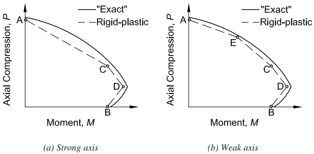
Figure description:
Interaction curves for Axial Compression and Moment
(a Strong axis
Legend
- "Exact" — color: black; symbol: Solid line
- Rigid-plastic — color: black; symbol: Dashed line
Annotations
- A (text_label - position: Moment = 0, Axial Compression = Max)
- C (text_label - position: Intermediate vertex on the dashed Rigid-plastic curve)
- D (text_label - position: Point of maximum Moment on the dashed Rigid-plastic curve)
- B (text_label - position: Axial Compression = 0 on the dashed Rigid-plastic curve)
| Point | Curve | Relative Moment, M | Relative Axial Compression, P |
|---|---|---|---|
| A | Both | 0 | Max |
| C | Rigid-plastic | High | High-Medium |
| D | Rigid-plastic | Max | Medium-Low |
| B | Rigid-plastic | High | 0 |
| (Exact Path) | "Exact" | Starts at A, smooth curve passing outside C and D, ends on M-axis slightly beyond B | - |
(b Weak axis
Legend
- "Exact" — color: black; symbol: Solid line
- Rigid-plastic — color: black; symbol: Dashed line
Annotations
- A (text_label - position: Moment = 0, Axial Compression = Max)
- E (text_label - position: First intermediate vertex on the dashed Rigid-plastic curve)
- C (text_label - position: Second intermediate vertex on the dashed Rigid-plastic curve)
- D (text_label - position: Point of maximum Moment on the dashed Rigid-plastic curve)
- B (text_label - position: Axial Compression = 0 on the dashed Rigid-plastic curve)
| Point | Curve | Relative Moment, M | Relative Axial Compression, P |
|---|---|---|---|
| A | Both | 0 | Max |
| E | Rigid-plastic | Medium-Low | High |
| C | Rigid-plastic | High | High-Medium |
| D | Rigid-plastic | Max | Medium-Low |
| B | Rigid-plastic | High | 0 |
| (Exact Path) | "Exact" | Starts at A, smooth curve passing outside E, C, and D, ends on M-axis slightly beyond B | - |
Notes: The plots compare interaction diagrams for axial compression (P and bending moment (M using 'Exact' (solid lines and 'Rigid-plastic' (dashed lines models for a structural member. The Rigid-plastic model is represented as a piecewise linear approximation inside the continuous 'Exact' curve.))))
Fig. C-II.1. Comparison between exact and simplified moment-axial compressive force cross-section strength envelopes.
and Lakshmi, 2001; Varma et al., 2002; Leon et al., 2007; Ziemian, 2010). For round HSS, these provisions allow for the increase of the usable concrete stress to 0.95 ′fc for calculating both axial compressive and flexural strengths to account for the ben- eficial effects of the confinement arising from the hoop action (Leon et al., 2007).
Based on similar assumptions, but allowing for slip between the steel beam and the composite slab, simplified expressions can also be derived for typical composite beam sections. Strictly speaking, these distributions are not based on slip, but on the strength of the shear connection. Full interaction is assumed if the shear connection strength exceeds that of either (a) the tensile yield strength of the steel section or the compressive strength of the concrete slab when the composite beam is loaded in positive moment, or (b) the tensile yield strength of the longitudinal reinforcing bars in the slab or the compressive strength of the steel section when loaded in negative moment.
When steel anchors are provided in sufficient numbers to fully develop this flexural strength, any slip that occurs prior to yielding has a negligible effect on behavior. When full interaction is not present, the beam is said to be partially composite. The effects of slip on the elastic properties of a partially composite beam can be significant and should be accounted for in calculations of deflections and stresses at service loads. Approximate elastic properties of partially composite beams are given in Commentary Section I3.
I1.2b Strain Compatibility Method
The principles used to calculate cross-sectional strength in Section II.2a may not be applicable to all design situations or possible cross sections. As an alternative, Section II.2b permits the use of a generalized strain-compatibility approach that allows the use of any reasonable uniaxial stress-strain model for the steel and concrete. This method is focused on ultimate strength and does not contemplate the use of pseudo-material properties to explicitly account for three-dimensional phenomena like local buckling and confinement that may arise in noncompact composite and slender-element composite sections. Refer to the effective stress-strain method for considering these phenomena.
I1.2c Elastic Stress Distribution Method
The use of an elastic stress distribution is recognized as being particularly relevant for the design of composite beams, encased composite members, and filled composite members for which the plastic stress distribution method is not applicable. Additional discussion for this method can be found in Commentary Sections I3.2a and I3.3.
I1.2d Effective Stress-Strain Method
This methodology provides one alternative for calculating the cross-section strength for composite members, including noncompact composite and slender-element composite cross sections. The effective stress-strain method is applicable when using a fiber-based approach for calculating the cross section axial force-moment strength interaction, while assuming strain compatibility and utilizing modified material
stress-strain curves to account implicitly for the effects of steel HSS local buckling, yielding, residual stresses, concrete cracking, concrete crushing, confinement, and any other effects that significantly impact the strength of the cross section (Sakino et al., 2004; Han et al., 2005; Liang, 2009; Lai and Varma, 2016).
I1.3 Material Limitations
The provisions of Chapter I were developed using experimental data in the bulk of literature, generally satisfying the range of material limitations given in Section II.3 (Ziemian, 2010; Hajjar, 2000; Shanmugam and Lakshmi, 2001; Varma et al., 2002; Leon et al., 2007). A limit of 10 ksi (69 MPa) is imposed on the concrete specified compressive strength for strength calculations unless the provisions of Appendix 2 are used, both to reflect the limited experimental data available above this strength and the changes in behavior observed (Varma et al., 2002). The specified minimum yield stress of the reinforcing bars is limited to a maximum value of 80 ksi (550 MPa). A lower limit of 3 ksi (21 MPa) is specified for both normal and lightweight concrete and an upper limit of 6 ksi (41 MPa) is specified for lightweight concrete to encourage the use of good quality, yet readily available, grades of structural concrete. The use of higher strengths in computing the modulus of elasticity and thus the stiffness of composite members for serviceability is permitted. However, the use of higher strengths in computing the strength of composite members is not permitted without appropriate testing and analyses. Alternatively, the provisions of Appendix 2 may be used for the design of rectangular filled composite members constructed from materials with higher strengths than those specified by the limits in Section II.3.
I1.4 Classification of Filled Composite Sections for Local Buckling
The behavior of filled composite members is fundamentally different from the behavior of hollow steel members. The concrete infill has a significant contribution to the stiffness, strength, and ductility of composite members. As the steel section area decreases, the concrete contribution becomes more significant.
For structural steel members, the terms “compact section” and “noncompact section” apply only to flexure and are related to the ability of the section to maintain a rotation capacity of approximately three before the onset of local buckling. For structural steel members, the terms “slender section” and “nonslender section” apply only to compression and are related to the ability of the section to reach column buckling strength before local buckling.
For filled composite members, the terms “compact composite section” and “noncompact composite section” apply to both flexure and compression and are not related to the rotation capacity. A compact composite section has sufficient element width-to-thickness ratio to develop yielding in longitudinal compression and provide confinement to the concrete infill to develop its compressive strength ( or ). A noncompact composite section has sufficient element width-to-thickness ratio to develop yielding in longitudinal compression, but not to confine the concrete infill. After exceeding a concrete compressive stress of , the volumetric dilation of the concrete increases, but the stiffness of steel elements (already yielded in longitudinal compression) is likely inadequate to confine the concrete infill, and the noncompact composite section undergoes volumetric dilation and local buckling.
A slender-element composite section has an element width-to-thickness ratio such that it can neither develop yielding of the steel in the longitudinal direction nor confine the concrete after it reaches compressive stress (Lai et al., 2014; Lai and Varma, 2015).
The elastic local buckling of the steel HSS is influenced significantly by the presence of the concrete infill. The concrete infill changes the buckling mode of the steel HSS (both within the cross section and along the length of the member) by preventing it from deforming inwards as shown in Figures C-II.2 and C-II.3. Bradford et al. (1998) analyzed the elastic local buckling behavior of filled composite compression members, showing that for rectangular steel HSS, the plate buckling coefficient, , in the elastic plate buckling equation (Ziemian, 2010) changes from 4.00 for hollow tubes to 10.6 for filled sections. As a result, the elastic plate buckling stress increases by a factor of 2.65 for filled sections as compared to HSS. Similarly, Bradford et al. (2002) showed that the elastic local buckling stress for filled round sections is 1.73 times that for hollow round sections.
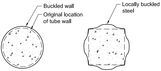
Figure description:
The image illustrates the cross-sectional buckling modes of concrete-filled steel tubes (HSS.
Key Entities and Details:
- Circular Section (Left:
- Original location of tube wall: Indicated by a dashed line.
- Buckled wall: Solid line showing outward deformation from the original circular shape.
- Concrete Infill: Represented by the speckled pattern inside the tube, preventing inward buckling.
- Rectangular Section (Right:
- Locally buckled steel: Solid lines showing the steel walls bulging outward on each side.
- Concrete Infill: Represented by the speckled pattern, constraining the steel to deform only in an outward direction.
Fig. C-II.2. Cross-sectional buckling mode with concrete infill.
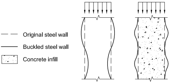
Figure description:
Key Information:
- Entities:
- Original steel wall: Represented by dashed vertical lines.
- Buckled steel wall: Represented by solid curved lines.
- Concrete infill: Represented by the stippled/textured area inside the second diagram.
- Applied Load: Indicated by downward arrows at the top of the columns.
- Observations:
- Left Diagram (No Infill: Shows a larger, single-wave buckling mode where the steel walls bow both inward and outward.
- Right Diagram (With Concrete Infill: Shows a higher-frequency buckling mode with multiple smaller waves. The concrete infill forces the steel to buckle only outward, as inward movement is restricted.
Fig. C-II.3. Changes in buckling mode with length due to the presence of infill.
For rectangular filled sections, the elastic local buckling stress, Fn, from the plate buckling equation simplifies to Equation I2-10. This equation indicates that yielding will occur for plates with b t less than or equal to 3 00 . E Fy, which designates the limit between noncompact composite and slender-element composite sections, λr. This limit does not account for the effects of residual stresses or geometric imper- fections because the concrete contribution governs for these larger b t ratios and the effects of reducing steel stresses is small. The maximum permitted b t value is based on the lack of experimental data above the limit of 5 00 . E Fy, and the potential effects (plate deflections and locked-in stresses) of concrete placement in extremely slender-element composite filled HSS cross sections. For flexure, the b t limits for the flanges are the same as those for walls in axial compression due to the similarities in loading and behavior. The compact/noncompact composite limit, λp, for webs in flexure was established conservatively as 3 00 . E Fy. The noncompact/ slender-element composite limit, λr, for the web was established conservatively as 5 70 . E Fy, which is also the maximum permitted for unfilled HSS. This limit was also established as the maximum permitted value due to the lack of experimental data and concrete placement concerns for thinner filled HSS cross sections (Lai et al., 2014).
For filled round HSS in axial compression, the noncompact/slender-element composite limit, , was established as , which is 1.73 times the limit of for unfilled round HSS. This was based on the findings of Bradford et al. (2002) and it compares well with experimental data. The maximum permitted equal to is based on the lack of experimental data and the potential effects of concrete placement in extremely slender-element composite filled HSS cross sections. For filled round HSS in flexure, the compact/noncompact composite limit, , in Table II.1b was developed conservatively as 1.25 times the limit for unfilled round HSS. The noncompact/slender-element composite limit, , was assumed conservatively to be the same as for unfilled round HSS, . This limit was also established as the maximum permitted value due to lack of experimental data and concrete placement concerns for thinner filled HSS cross sections (Lai and Varma, 2015).
I1.5 Stiffness for Calculation of Required Strengths
This section along with Chapter C forms the basis of the direct analysis method of design for structural systems including encased composite members or filled composite members or composite plate shear walls. The method is identical to the method for structural steel sections alone with the exception of the adjustments to stiffness prescribed for the analysis to determine required strengths.
Stiffness Reduction Parameter, . The reduced stiffness, , where is as calculated in Section I2, and , mirrors that used for bare steel. For frames with slender composite members, where the limit state is governed by elastic stability, the factor of on the effective flexural stiffness results in a system available strength equal to 0.64 times the elastic stability limit. This approximates the margin of safety implied in the design provisions for slender composite columns by the effective length procedure, where from Equation I2-3, . Second, for frames with intermediate or stocky
columns, the factor reduces the stiffness to account for inelastic softening (for example, concrete cracking and steel partial yielding) prior to the members reaching their design strength.
Unlike for bare steel, the factor is a constant value and does not vary with required axial compressive strength. As a consequence, the use of by applying additional notional load, such as described in Section C2.3(c), is inaccurate and not permitted. For the case of a structure containing both composite members and highly loaded ( ) bare steel members, a conservative approach to avoid a variable stiffness in the analysis would be to apply the additional notional load so that can be used for the bare steel members and maintain for the composite members.
Research indicates that the stiffness prescribed in this section may result in unconservative errors for very stability sensitive structures (Denavit et al., 2016a). The Specification has traditionally not accounted for long-term effects due to creep and shrinkage; as such, the stiffness prescribed in this section was developed based on studies examining only short-term behavior. Refer to Commentary Sections II and I3.2 for additional discussion.
The use of reduced stiffness only pertains to analyses for strength and stability limit states. It does not apply to analyses for other stiffness-based conditions and criteria, such as for drift, deflection, vibration, and period determination. The effective stiffness, , has been found to provide a reasonable value for use in determining drifts (Denavit et al., 2018).
This section does not apply to the effective length method. It is recommended that when using the effective length method with composite compression members that either (a) the nominal stiffness be taken as the effective stiffness, , and the interaction strength of Section H1.1 be used, or (b) the nominal stiffness be taken as 0.8 times the effective stiffness, , and the interaction strength be determined using one of the methods described in Commentary Section I5.
Composite Plate Shear Wall Effective Stiffness. The stiffness of composite plate shear walls must account for the extent of concrete cracking corresponding to the calculated required strengths. These stiffnesses can be estimated conservatively using equations developed in Agarwal et al. (2020) for uncoupled composite plate shear walls. The effective stiffness of composite plate shear walls can be approximated reasonably using Equation II-1. This stiffness, , is representative of the secant stiffness corresponding to of the flexural capacity, , of walls subjected to axial compression of about of the concrete capacity, . Equation II-2 for axial stiffness was calibrated to match the concrete cracking associated with the flexural stiffness of Equation II-1. Equation II-3 corresponds to the use of uncracked shear stiffness of composite plate shear walls. Composite walls with overall height-to-length ratio greater than or equal to 3.0 will be flexure dominant, and the shear stiffness can be approximated using uncracked values. When drift limits and stiffness requirements govern design, composite walls may be overdesigned with respect to the required strengths. Overdesigned walls may endure less concrete cracking and their stiffness may be underestimated using Equations II-1 to II-3. In such cases, it
may be appropriate to use rational analysis methods to estimate the flexural stiffness of the walls, while accounting for the extent of concrete cracking corresponding to the calculated required strength.
I1.6 Requirements for Composite Plate Shear Walls
Composite plate shear walls consist of steel modules that are filled with concrete. The steel modules consist of steel plates connected with tie bars and with steel headed stud anchors on the interior surfaces to develop composite action between the steel plates and the concrete infill. The wall ends are closed using flange (closure) plates or boundary elements as shown in Figure C-I1.4. Steel headed stud anchors
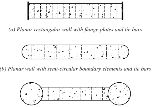
Figure description:
Composite Plate Shear Wall Cross-Sections
- Materials: Concrete infill with steel exterior plates and internal tie bars (dashed vertical lines.
- Configuration (a: Planar rectangular wall utilizing flat flange plates at the ends.
- Configuration (b: Planar wall utilizing semi-circular boundary elements at the ends.
- Configuration (c: Planar wall utilizing full circular boundary elements at the ends.
(c) Planar wall with circular boundary elements and tie bars
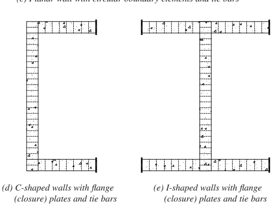
Figure description:
The image displays cross-sectional diagrams of filled composite plate shear walls, illustrating two configurations:
- (d C-shaped walls: A composite wall section forming a 'C' shape. It features flange (closure plates at the ends and internal tie bars within the concrete-filled steel plate boundary elements.
- (e I-shaped walls: A composite wall section forming an 'I' shape. Similar to the C-shape, it utilizes flange (closure plates and internal tie bars for structural reinforcement within the concrete-filled sections.
Fig. C-11.4. Filled composite plate shear walls with boundary elements or flange (closure) plates.
may be used to replace some rows or columns of tie bars. Coupled wall systems may consist of two or more walls connected by coupling beams. The coupling beams may be filled composite members or steel members.
The two steel plates of composite plate shear walls must be connected using tie bars. These tie bars govern the structural behavior and stability of the empty steel modules before concrete placement. Additional steel headed stud anchors may be used along with tie bars to reduce the slenderness and improve the stability of steel plates after concrete placement.
Composite plate shear walls are referred to as steel plate composite (SC) walls in the design of safety-related nuclear structures according to the AISC Specification for Safety-Related Steel Structures for Nuclear Facilities (AISC, 2018b) and the corresponding AISC Design Guide 32, Design of Modular Steel-Plate Composite Walls for Safety-Related Nuclear Facilities (Bhardwaj and Varma, 2017). The requirements in this Specification are similar, but independent of the requirements for SC walls in nuclear facilities. In building structures, composite plate shear walls are used primarily as slender (overall height-to-length ratio greater than or equal to 3) shear walls or core wall structures. In nuclear structures, the entire structural system consists of several interconnected short squat walls, typically with overall height-to- length ratio less than or equal to 2.
The steel plate reinforcement ratio limits are based on the range available from experiments. Walls without flange (closure) plates or boundary elements have been tested by Kurt et al. (2016). While the behavior may be acceptable, their construction can be difficult due to the absence of closure plates and need for additional formwork.
Seismic provisions for the design of uncoupled and coupled composite plate shear walls—concrete filled are included in the AISC Seismic Provisions for Structural Steel Buildings (AISC, 2022c), NEHRP Recommended Seismic Provisions for New Buildings and Other Structures (FEMA, 2020), and ASCE/SEI 7, Minimum Design Loads and Associated Criteria for Buildings and Other Structures (ASCE, 2022). These seismic design provisions build upon the requirements for composite plate shear walls in this Specification.
AISC Design Guide 38, SpeedCore Systems for Steel Structures (Varma et al., 2022) includes detailed guidance along with examples for the design of composite plate shear wall—concrete filled (C-PSW/CF) systems, whether coupled or uncoupled, for wind, seismic, and fire loading conditions.
I1.6a Slenderness Requirement
The steel plates of composite plate shear walls are required to be nonslender, in other words, yielding in compression must occur before local buckling. When subjected to compressive stresses, the plate undergoes local buckling between the steel tie bars or steel anchors. The lines joining the steel tie bars or anchors act as fold lines, and local buckling occurs between them. The buckling mode indicates fixed ends along the vertical lines with steel anchors, and partial fixity along the vertical lines between steel anchors. Experimental studies have been conducted to evaluate the effects of
plate slenderness ratio, , defined as the largest clear distance between rows of steel anchors or tie bars, , divided by the plate thickness, , on local buckling of plates (Zhang et al., 2014, 2020), leading to Equation I1-4 for the slenderness limit for nonseismic conditions. Because tie bars may also act as anchors, the equation considers the largest unsupported length between rows of steel anchors or tie bars, . When slenderness exceeds the limit of Equation II-4, local buckling will occur when the compressive stress reaches , which can be calculated using Equation C-II-1, and the compressive strength of the composite wall section can be estimated using Equation C-II-2 (Zhang et al., 2020).
(C-I1-1)
(C-II-2)
I1.6b Tie Bar Requirement
The tie bar spacing requirement is based on the flexibility and shear buckling of empty steel modules before concrete placement (Varma et al., 2019). The flexibility of the empty modules for transportation, shipping, and handling activities is dominated by their effective shear stiffness, , which can be estimated using models (Varma et al., 2019) or calculated conservatively for a unit cell of the module using Equation C-11-3:
(C-II-3)
In this equation, represents the moment of inertia of the steel faceplates. The variable represents the tie bar spacing. The variable is the ratio of the flexural stiffness of the steel plate to the flexural stiffness of the tie bar and simplifies to the form of Equation 11-6.
After assembly and before concrete casting, the empty modules provide structural support for construction activities, loads, and the steel framework connected to it. The buckling of the empty module subjected to compression loading is also governed by its effective shear stiffness, , and can be estimated conservatively using Equation C-11-4:
(C-II-4)
At the limit, the requirements of Equation II-5 and II-6 will result in a critical buckling stress equal to 1 ksi (6.9 MPa), which is equivalent to a distributed loading of 12 kip/ft (175 000 N/m) for walls with two 1/2-in.- (13-mm-) thick steel plates. The stresses and deflections induced by concrete casting hydrostatic pressure can also be estimated as shown in Varma et al. (2019). Bhardwaj et al. (2018) indicate that modules that meet the plate slenderness requirement of Section II.6b can be typically cast with concrete pour heights of up to 30 ft (9.1 m) without significant influence of induced deflections and stresses on the compressive strength and buckling of the steel plates.