C-I8I8 Steel anchors
PDF page 530 · AISC 360-22
I8.1 General
This section covers the strength, placement, and limitations on the use of steel anchors in composite construction. The term “steel anchor,” first introduced in the 2010 AISC Specification (AISC, 2010), includes the traditional “shear connector,” now defined as a “steel headed stud anchor” and a “steel channel anchor” both of which have been part of previous Specifications. Both steel headed stud anchors and hot-rolled steel channel anchors are addressed in the Specification. The design provisions for steel anchors are given for composite beams with solid slabs or with formed steel deck and for composite components. A composite component is defined as a member, connecting element, or assemblage in which steel and concrete elements work as a unit in the distribution of internal forces. This term excludes composite beams with solid slabs or formed steel deck. The provisions for composite components include the use of a resistance factor or safety factor applied to the nominal strength of the steel anchor, while for composite beams, the resistance factor and safety factor are part of the composite beam resistance and safety factor.
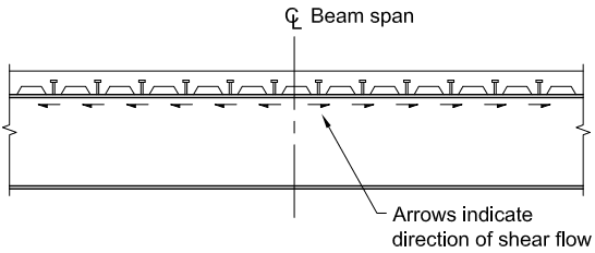
Figure description:
Key Information:
- Subject: Diagram of shear flow in a composite beam under gravity loads.
- Entities:
- Steel Beam: Longitudinal structural member.
- Formed Steel Deck: Profiles resting on the beam.
- Steel Headed Stud Anchors: Vertical connectors attached to the beam through the deck.
- Centerline (CL: Represents the mid-span of the beam.
- Action: Arrows indicate the direction of shear flow, moving away from the center of the beam span toward the supports on both sides.
(a) Shear flow due to gravity loads only
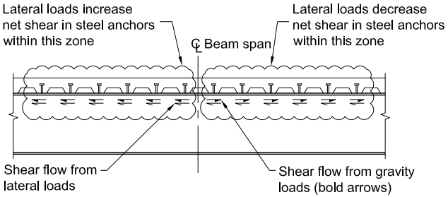
Figure description:
Structural Diagram: Shear Flow in Composite Beam
- Entities:
- Steel Anchors (Headed Studs: Connect the concrete slab/decking to the steel beam.
- Beam Span Centerline (: Divides the beam into two zones.
- Shear Flow Components:
- Gravity Loads: Represented by bold arrows pointing away from the beam centerline.
- Lateral Loads: Represented by thin arrows pointing in a single direction (left to right across the entire span.
- Key Observations:
- Left Zone: Lateral loads and gravity loads act in the same direction, increasing the net shear in the steel anchors.
- Right Zone: Lateral loads and gravity loads act in opposite directions, decreasing the net shear in the steel anchors.
(b) Shear flow due to gravity and lateral loads in combination
Fig. C-17.1. Shear flow at collector beams.
Specification for Structural Steel Buildings, August 1, 2022 AMERICAN INSTITUTE OF STEEL CONSTRUCTION
Steel headed stud anchors up to 1 in. (25 mm) in diameter are permitted for use in beams with solid slabs based on a review of available data and their history of successful performance in bridge applications. The limitation of 3/4 in. (19 mm) anchors for all other conditions represents the limits of push-out data for decked members as well as the limits of applicability of the current composite component provisions. Though larger anchors for use in composite components are not addressed by this Specification, their strength may be determined by ACI 318, Chapter 17 (ACI, 2019).
Studs not located directly over the web of a beam tend to tear out of a thin flange before attaining full shear strength. To guard against this contingency, the size of a stud not located over the beam web is limited to times the flange thickness (Goble, 1968). The practical application of this limitation is to select only beams with flanges thicker than the stud diameter divided by 2.5 .
Section I8.2 requires a minimum overall steel headed stud anchor height to the shank diameter ratio of 4 when calculating the nominal shear strength of a steel headed stud anchor in a composite beam. This requirement has been used in previous Specifications and has had a record of successful performance. For calculating the nominal shear strength of a steel headed stud anchor in other composite components, Section I8.3 increases this minimum ratio to 5 for normal weight concrete and 7 for lightweight concrete. Additional increases in the minimum ratio are required for computing the nominal tensile strength or the nominal strength for interaction of shear and tension in Section I8.3. The provisions of Section I8.3 also establish minimum edge distances and center-to-center spacings for steel headed stud anchors if the nominal strength equations in that section are to be used. These limits are established in recognition of the fact that only steel failure modes are checked in the calculation of the nominal anchor strengths in Equations I8-3, I8-4, and I8-5. Concrete failure modes are not checked explicitly in these equations (Pallarés and Hajjar, 2010a, 2010b), whereas concrete failure is checked in Equation I8-1. This is discussed further in Commentary Section I8.3.
I8.2 Steel Anchors in Composite Beams
I8.2a Strength of Steel Headed Stud Anchors
The present strength equations for composite beams and steel headed stud anchors are based on the considerable research that has been published, such as Jayas and Hosain (1988a, 1988b), Mottram and Johnson (1990), Easterling et al. (1993), and Roddenberry et al. (2002a). Equation I8-1 contains and factors to bring these composite beam strength requirements to a comparable level with other codes around the world. Other codes use a stud strength expression similar to this Specification, but the stud strength is reduced by a factor of 0.8 in the Canadian code (CSA, 2009) and by an even lower partial safety factor, , for the corresponding stud strength equations in Eurocode 4 (CEN, 2009). This Specification includes the stud anchor resistance factor as part of the overall composite beam resistance factor.
The majority of composite steel floor decks used today have a stiffening rib in the middle of each deck flute. Because of the stiffener, studs must be welded off-center in the deck rib. Studies have shown that steel studs behave differently depending upon their location within the deck rib (Lawson, 1992; Easterling et al., 1993;
Van der Sanden, 1996; Yuan, 1996; Johnson and Yuan, 1998; Roddenberry et al., 2002a, 2002b). The so-called “weak” (unfavorable) and “strong” (favorable) positions are illustrated in Figure C-I8.1. Furthermore, the maximum value shown in these studies for studs welded through steel deck is on the order of to . Studs placed in the weak position have strengths as low as .
The strength of steel headed stud anchors installed in the ribs of concrete slabs on formed steel deck with the ribs oriented perpendicular to the steel beam is reasonably estimated by the strength of steel headed stud anchors computed from Equation I8-1, which sets the default value for steel headed stud anchor strength equal to that for the weak stud position. Both AISC (1997a) and the Steel Deck Institute (SDI, 2001) recommend that studs be detailed in the strong position, but ensuring that studs are placed in the strong position is not necessarily an easy task because it is not always easy for the installer to determine where along the beam the particular rib is located relative to the end, midspan, or point of zero shear. Therefore, the installer may not be clear on which location is the strong and which is the weak position.
In most composite floors designed today, the ultimate strength of the composite section is governed by the strength of the shear connection, as full composite action is typically not the most economical solution to resist the required strength. The degree of composite action, as represented by the ratio of the total shear connection strength divided by the lesser of the yield strength of the steel cross section and the compressive strength of the concrete slab, , influences the flexural strength as shown in Figure C-I8.2.
It can be seen from Figure C-I8.2 that a relatively large change in shear connection strength results in a much smaller change in flexural strength. Thus, formulating the influence of steel deck on shear anchor strength by conducting beam tests and backcalculating through the flexural model, as was done in the past, leads to an inaccurate assessment of stud strength when installed in metal deck.
The changes in steel headed stud anchor requirements that occurred in the 2005 AISC Specification (AISC, 2005b) were not a result of either structural failures or performance problems. Designers concerned about the strength of existing structures based on earlier Specification requirements should note that the slope of the curve shown in Figure C-I8.2 is rather flat as the degree of composite action approaches one. Thus, even a large change in steel stud strength does not result in a proportional decrease of the flexural strength. In addition, the current expression does not account
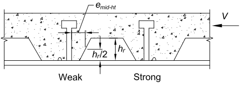
Figure description:
- Subject: Diagram illustrating "Weak" vs. "Strong" headed stud anchor positions in a composite steel deck system.
- Shear Force (: Horizontal force acting on the concrete slab.
- Rib Geometry: Defined by rib height ( and its mid-height (.
- Eccentricity (: Distance from the stud centerline to the rib wall, measured at the rib's mid-height (.
- Key Entities:
- Weak Position: Stud located with less concrete mass behind it relative to the direction of force .
- Strong Position: Stud located with more concrete mass behind it relative to the direction of force .
- Source: Roddenberry et al. (2002b.
Fig. C-I8.1. Weak and strong stud positions (Roddenberry et al., 2002b).
for all the possible shear force transfer mechanisms, primarily because many of them are difficult or impossible to quantify. However, as noted in Commentary Section I3.1, as the degree of composite action decreases, the deformation demands on steel studs increase. This effect is reflected by the increasing slope of the relationship shown in Figure C-I8.2 as the degree of composite action decreases. Thus, designers should consider the influence of increased ductility demand, when evaluating existing composite beams with less than 50% composite action.
The reduction factor, , for steel headed stud anchors used in composite beams with no decking was reduced from 1.0 to 0.75 in the 2010 AISC Specification. The methodology used for steel headed stud anchors that incorporates and was implemented in the 2005 AISC Specification. The research (Roddenberry et al., 2002a) in which the factors and were developed focused almost exclusively on cases involving the use of steel headed stud anchors welded through the steel deck. The research pointed to the likelihood that the solid slab case should use ; however, the body of test data had not been established to support the change. More recent research has shown that the 0.75 factor is appropriate (Pallarés and Hajjar, 2010a).
I8.2b Strength of Steel Channel Anchors
Equation I8-2 is a modified form of the formula for the strength of channel anchors presented in Slutter and Driscoll (1965), which was based on the results of pushout tests and a few simply supported beam tests with solid slabs by Viest et al. (1952). The modification has extended its use to lightweight concrete.
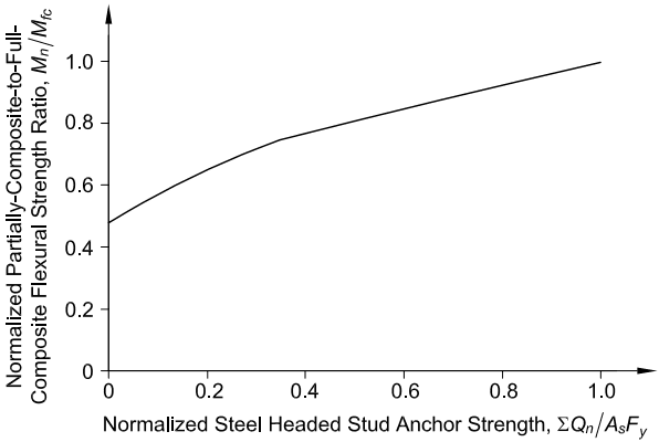
Figure description:
Normalized Flexural Strength Ratio vs. Normalized Stud Anchor Strength
Relationship between Normalized Steel Headed Stud Anchor Strength and Normalized Flexural Strength Ratio
| Normalized Steel Headed Stud Anchor Strength, ΣQ_n/A_sF_y | Normalized Partially-Composite-to-Full-Composite Flexural Strength Ratio, M_n/M_fc |
|---|---|
| 0.0 | 0.48 |
| 0.1 | 0.57 |
| 0.2 | 0.65 |
| 0.3 | 0.72 |
| 0.4 | 0.77 |
| 0.5 | 0.81 |
| 0.6 | 0.85 |
| 0.7 | 0.89 |
| 0.8 | 0.93 |
| 0.9 | 0.97 |
| 1.0 | 1.00 |
Notes: The data points are estimated based on visual inspection of the graph. The curve shows a distinct change in slope around the normalized strength value of 0.35 to 0.4.
Fig. C-18.2. Normalized flexural strength versus normalized steel headed stud anchor (Easterling et al., 1993).
Eccentricities need not be considered in the weld design for cases where the welds at the toe and heel of the channel are greater than 3/16 in. (5 mm) and the anchor meets the following requirements:
where
| H = height of anchor, in. (mm) |
| Lc = length of anchor, in. (mm) |
| R = radius of the fillet between the flange and the web of the channel anchor, in. (mm) |
| tf = thickness of channel anchor flange, in. (mm) |
| tw = thickness of channel anchor web, in. (mm) |
I8.2d Detailing Requirements
Uniform spacing of steel anchors is permitted, except in the presence of heavy concentrated loads.
The minimum distances from the center of an anchor to a free edge in the direction of the shear force that are shown in this Specification are based on data reported by Nelson Stud Welding Division (Nelson, 1977). Data for various steel headed stud anchor diameters, concrete compressive strengths, and unit weights are reported. The provisions selected for inclusion in this Specification result in no reduced strength for 3/4-in.- (19-mm-) diameter steel headed stud anchors in 4 ksi (28 MPa) concrete, which were deemed to be representative of most composite beam construction. Other values are available in the report for use by the designer if deemed to be more applicable.
The minimum spacing of anchors along the length of the beam, in both flat soffit concrete slabs and in formed steel deck with ribs parallel to the beam, is six diameters (6d); this spacing reflects the development of shear planes in the concrete slab (Ollgaard et al., 1971). Because most test data are based on the minimum transverse spacing of four diameters (4d), this transverse spacing was set as the minimum permitted. If the steel beam flange is narrow, this spacing requirement may be achieved by staggering the studs with a minimum transverse spacing of three diameters (3d) between the staggered row of studs. When deck ribs are parallel to the beam and the design requires more studs than can be placed in the rib, the deck may be split so that adequate spacing is available for stud installation. Figure C-I8.3 shows possible anchor arrangements.
I8.3 Steel Anchors in Composite Components
This section applies to steel headed stud anchors used primarily in the load transfer (connection) region of composite compression members and beam-columns, encased and filled composite beams, composite coupling beams, and composite walls, where the steel and concrete are working compositely within a member. An example of the use of steel headed stud anchors in a composite wall is shown in Figure C-I8.4. In such cases, it is possible that the steel headed stud anchor will be subjected to shear, tension, or interaction of shear and tension. As the strength of the steel headed stud anchors in the load transfer region must be assessed directly, rather than implicitly within the strength assessment of a composite member, a resistance or safety factor should be applied, comparable to the design of bolted connections in Chapter J.
These provisions are not intended for hybrid construction where the steel and concrete are not working compositely, such as with embed plates. Section I8.2 specifies the strength of steel headed stud anchors embedded in a solid concrete slab or in a concrete slab with formed steel deck in a composite beam.
Data from a wide range of experiments indicate that the failure of steel headed stud anchors subjected to shear occurs in the steel shank or weld in a large percentage of cases if the ratio of the overall height-to-shank diameter of the steel headed stud anchor is greater than 5 for normal weight concrete. In the case of lightweight concrete, the necessary minimum ratio between the overall height of the stud and the diameter increases up to 7 (Pallarés and Hajjar, 2010a). Use of anchors meeting the dimensional limitations for shear loading preclude the limit state of concrete pryout as defined by ACI 318, Chapter 17 (ACI, 2019). A similarly large percentage of failures occur in the steel shank or weld of steel headed stud anchors subjected to tension or interaction of shear and tension if the ratio of the overall height to shank diameter of the steel headed stud anchor is greater than 8 for normal weight concrete. In the case of lightweight concrete, the necessary minimum ratio between the overall height of the stud and the diameter increases up to 10 for steel headed stud anchors subjected to tension (Pallarés and Hajjar, 2010b). For steel headed stud anchors subjected to interaction of shear and tension in lightweight concrete, there are so few experiments available that it is not possible to discern sufficiently when the steel material will control the failure mode. For the strength of steel headed stud anchors
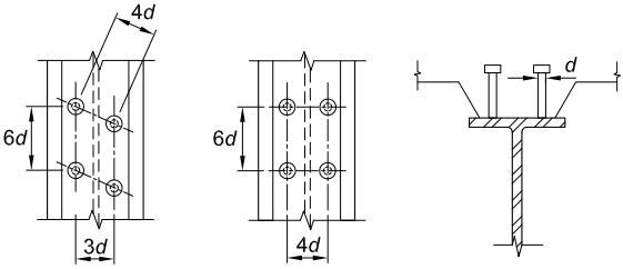
Figure description:
Key Information: Steel Anchor Arrangements
- Entities: Steel headed stud anchors, steel beam flange.
- Dimensional Parameter (: Shank diameter of the steel headed stud anchor.
- Staggered Arrangement (Plan View:
- Longitudinal spacing between rows:
- Transverse spacing between columns:
- Diagonal spacing between adjacent studs:
- Grid Arrangement (Plan View:
- Longitudinal spacing between rows:
- Transverse spacing between columns:
- Cross-Section View: Shows headed studs welded to the top flange of a steel beam, defining the diameter .
Fig. C-I8.3. Steel anchor arrangements.
Specification for Structural Steel Buildings, August 1, 2022 AMERICAN INSTITUTE OF STEEL CONSTRUCTION
in lightweight concrete subjected to interaction of shear and tension, it is recommended that the provisions of ACI 318, Chapter 17, be used. Use of steel headed stud anchors meeting the dimensional limitations for tension loading preclude the limit states of concrete breakout and pryout as defined by ACI 318, Chapter 17, where analysis indicates no cracking at service load levels, as would generally be the case in compression zones and regions of high confinement typical of composite construction. Where the engineer determines that concrete cracking under service load levels can occur, it is recommended that the provisions of ACI 318, Chapter 17, be used.
The use of edge distances in ACI 318, Chapter 17, to compute the strength of a steel anchor subjected to concrete crushing failure is complex. It is rare in composite construction that there is a nearby edge that is not uniformly supported in a way that prevents the possibility of concrete breakout failure due to a close edge. Thus, for brevity, the provisions in this Specification simplify the assessment of whether it is warranted to check for a concrete failure mode. Additionally, if an edge is supported uniformly, as would be common in composite construction, it is assumed that a concrete failure mode will not occur due to the edge condition. Thus, if these provisions are to be used, it is important that it be deemed by the engineer that a concrete breakout failure mode in shear is directly avoided through having the edges perpendicular to the line of force supported, and the edges parallel to the line of force sufficiently distant that concrete breakout through a side edge is not deemed viable. For loading in shear, the determination of whether breakout failure in the concrete is a viable
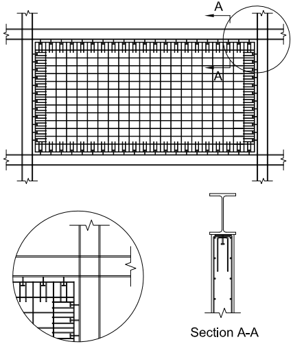
Figure description:
Key Information: Fig. C-I8.4 Typical Reinforcement Detailing
- Subject: Structural detailing for steel headed stud anchors in a composite wall subjected to tension.
- Main Elevation:
- Shows a rectangular concrete wall panel framed by steel members.
- Displays a dense grid of horizontal and vertical reinforcement bars.
- Features a perimeter of steel headed stud anchors connecting the concrete infill to the boundary steel frame.
- Detail View (Circular Inset:
- Close-up of the upper-right corner junction between the steel frame and the reinforced concrete wall.
- Illustrates the placement of headed studs and reinforcement bar termination at the boundary.
- Section A-A:
- Cross-section of the wall showing an I-beam top flange.
- Depicts the steel headed stud anchor welded to the beam flange and embedded in concrete.
- Shows U-shaped hairpins/supplemental reinforcement wrapping around the anchors and longitudinal reinforcement bars.
Fig. C-18.4. Typical reinforcement detailing in a composite wall for steel headed stud anchors subjected to tension.
failure mode for the steel headed stud anchor is left to the engineer. Alternatively, the provisions call for required anchor reinforcement with provisions comparable to those of ACI 318, Section 17.5.2.1. In addition, the provisions of the applicable building code or ACI 318, Chapter 17, may be used directly to compute the strength of the steel headed stud anchor.
The steel limit states, resistance factors, and corresponding safety factors covered in this section match with the corresponding limit states of ACI 318, Chapter 17, although they were assessed independently for these provisions. As only steel limit states are required to be checked if there are no edge conditions, experiments that satisfy the minimum height-to-diameter ratio, but that included failure of the steel headed stud anchor either in the steel or in the concrete, were included in the assessment of the resistance and safety factors (Pallarés and Hajjar, 2010a, 2010b).
For steel headed stud anchors subjected to tension or combined shear and tension interaction, it is recommended that anchor reinforcement always be included around the stud to mitigate premature failure in the concrete. If the ratio of the diameter of the head of the stud to the shank diameter is too small, the provisions call for use of ACI 318, Chapter 17, to compute the strength of the steel headed stud anchor. If the distance to the edge of the concrete or the distance to the neighboring anchor is too small, the provisions call for required anchor reinforcement with provisions comparable to those of ACI 318, Section 17.5.2.1. Alternatively, the provisions of the applicable building code or ACI 318, Chapter 17, may also be used directly to compute the strength of the steel headed stud anchor.
I8.4 Performance-Based Alternative for the Design of Shear Connection
In 2022, provisions for performance-based design of the shear connection were introduced. The provisions provide requirements for quantifying the mechanical properties of the shear connection. They can be used to overcome the geometric limitations, such as deck profile height or connector spacing contained in Sections I3.2c, I8.1, and I8.2. Furthermore, the same principle applies to the material limitations of the shear connection types currently prescribed by the Specification. Also, they can be used to quantify the necessary design parameters for alternatives, such as those incorporating nonwelded fasteners, welded plate connectors, specific geometric features of the formed steel deck, etc. Another benefit of the performance-based evaluation path is the ability to directly capture incidental contribution on the performance of various elements of the shear connection assembly, such as the deck profile, otherwise not explicitly recognized by the Specification. Finally, accuracy, reliability, and economy can be improved by generating available strength, performance characteristics, and constitutive models relative to each individual configuration of shear connection. The intent of the provisions prescribing performance-based alternatives for the design of the shear connection is not to alter the specification provision governing the determination of flexural strength of the composite member whose shear connection strength is established through the performance-based path.
These provisions provide two implementation paths—one based on assurance of equivalent performance relative to the shear connections covered by the scope of Section I8.3, and the other based on a direct analytical implementation of performance
characteristics that either do not meet, or exceed those characteristic for the methods of shear connections currently stipulated by Section I8.3.
Aside from the relevant shear connection strength, , the performance of the shear connection is further dictated by the presumptive values of slip capacity, composite beam or component reliability, geometric and material constraints of evaluated shear connection, and shear connection stiffness.
I8.4a Test Standard
The Specification provisions relative to shear connection strength have traditionally been based on the body of data generated through push-out tests (Ollgaard et al., 1971; Lyons et al., 1994; Rodenberry et al., 2002a, 2002b). While no formal or codified test protocol had traditionally existed aside from Annex A of EN-1994-1-1 (CEN, 2009), the key elements of the procedure have remained relatively unchanged. Evaluation services, such as the International Code Council Evaluation Services (ICC-ES) and the International Association of Plumbing and Mechanical Officials Uniform Evaluation Services (IAPMO UES), have published evaluation criteria leading to the establishment of formal procedures for quantifying shear connection mechanical properties (IAPMO, 2015; IAPMO, 2018). The most typical implementation venue for these protocols involves a pursuit of an evaluation report, which serves as a basis of acceptance by the authority having jurisdiction.
To facilitate the development of its own composite design provisions, AISI has published AISI S923 (AISI, 2020a), a testing standard for the assessment of shear connection performance in composite steel-concrete members. This standard serves as the basis of evaluation using this provision of the Specification, though comparable alternatives, depending on their scope and provided their acceptability to the authority having jurisdiction, such as those aforementioned, could be employed. AISI also published a companion standard AISI S924 (AISI, 2020b) for the assessment of composite section stiffness, which can be employed in conjunction with any particular method of shear connection.
Other similar protocols are provided by EN1994-1-1 Annex A (CEN, 2009), IAPMO UES EC-023 (IAPMO, 2015), and EC-033 (IAPMO, 2018). AISI S923 is general in scope. The other protocols mentioned, while equivalent in application, are generally specific in terminology and configuration to specific types of shear connectors. The users, as an alternative, may for convenience choose to apply these other protocols instead of AISI S923.
I8.4b Nominal and Available Strength
Nominal strength of the shear connection is necessary for the calculation of composite member connection strength. Available strength is used for the connection component strength. The coefficient of 0.85 represents an adjustment to account for the statistical bias factor (Mujagic and Easterling, 2009) relative to the strength computation model for headed shear studs developed by Rodenberry et al. (2002a, 2002b). The application of the bias factor adjustment, in addition to the acceptance criteria outlined in Section I8.4d, assures the usage of the strength reduction factors presently stipulated by this Specification. Alternatively, the bias factor can be
removed and a separate strength reduction factor can be calculated using the data directly, in lieu of those provided by this Specification.
I8.4c Shear Connection Slip Capacity
Starting with its 2016 edition, the Specification has explicitly required the consideration of shear connection ductility, also defined by the term slip capacity, in the assessment of composite beam available strength. The commentary provides additional guidelines on the methods for considering shear connection slip capacity. Many typical shear connection assemblies exhibit a nominally elastic-perfectly-plastic load-slip response, with a slightly descending response curve. The factor of 0.95 , also commonly used in other similar contexts, provides for the consideration of capturing considerable and structurally useful slip capacity and an inconsequential loss of strength in a ductile assembly.
I8.4d Acceptance Criteria
The conditions (1) through (3), in addition to the requirements of Sections I8.4a through I8.4c, aim at providing for the usage of alternative shear connection methods based on equivalency in performance to the methods currently recognized by Section I8.3.
Reliability assessment of composite beams, even in its simplest first-order second-moment formulation, is a complex effort, impractical to undertake on a case-by-case basis, greatly influenced by geometric parameters, mechanical properties of the components of a composite section, and the consequent position of the neutral axis in the section. When composite beams are partially composite, the coefficient of variation relative to the influence of shear connection on the composite beam strength becomes a function whose influence varies based on the degree of composite action, the governing failure mode, and other factors. The strength reduction factor currently stipulated by the Specification relative to the strength prediction model for the shear connection, when used for connection component design, or the strength reduction factor used in composite beams based on the model by Roddenberry et al. (2002a, 2002b) reflect an upper limit of 0.18 on the coefficient of variation relative to the influence of shear connection, along with a governing bias factor of 1.17, characteristic for solid slab configurations (Mujagic and Easterling, 2009). The original reliability analyses leading to the current strength reduction factor operated with a considerable data space. As assessment of the performance of individual connection configurations is typically based on a limited number of tests, the effect of the standard error of the mean could become pronounced. For this reason, two thresholds were provided scaling the coefficient of variation of 0.18 to 0.15 and 0.09 for the data space of nine and four replicate tests, respectively.
The Specification requirement to establish the effect of shear connection ductility still applies. The value of 0.25 in. (6 mm) represents the threshold ductility value for a 3/4-in.- (19-mm-) diameter steel headed stud anchor in a solid slab upon which the previous Specification editions have implicitly been based. Alternative methods of shear connection that meet this requirement are subject to the same commentary guidelines on ductility as provided for the conventional shear connection in Commentary Section I3.2d.
While elastic shear stiffness is traditionally related to serviceability considerations, the concern for an early departure from a typical load-slip relationship, despite the ductility ultimately achieved, could cause premature discontinuities in the composite section strain diagram and invalidate basic design and analysis assumptions. For this reason, the acceptance limit on minimum shear elastic stiffness has been imposed. While subject to the influence of variables, such as the modulus of elasticity of steel and the surrounding concrete, stud position relative to deck rib, etc., the value of 2,000 kip/in. (350 000 N/mm), determined as the slope of the load-slip line between the points of 10 and of the ultimate load, is a typical upper-bound value seen in push-out tests (Lyons et al., 1994; Rodenberry et al., 2002a, 2002b) and predicted by the proposed analytical models (Oehlers and Coughlan, 1986; Xu and Liu, 2019).
Condition (4) allows the Specification user to circumvent the acceptance conditions (1) through (3) and the application of the bias factor of Section I8.4b by capturing the effects of different performance thresholds directly in the design, whether determining the available or required strength.