C-I2I2 Axial force
PDF page 497 · AISC 360-22
The design of encased and filled composite members is treated separately, although they have much in common. The intent is to facilitate design by keeping the general principles and detailing requirements for each type of compression member separate.
An ultimate strength cross-section model is used to determine the section strength (Leon et al., 2007; Leon and Hajjar, 2008). This model is similar to that used in previous LRFD Specifications. The design equations in Section I2 for computing compressive axial strength including length effects apply only to doubly symmetric sections. For singly symmetric and unsymmetric sections, only the strain compatibility approach utilizing reasonable limitations on strains (for example, 0.003 for concrete and 0.02 for steel) is applicable for determining cross-sectional strength. As for steel-only columns, more advanced methods are necessary to design singly symmetric and unsymmetric columns to include length effects. Generalized approaches, such as those in Chapters E and F for steel-only columns, are not yet available for composite columns as the variety of sections possible does not lend itself to simplifications.
The design for length effects is consistent with that for steel compression members. The equations used are the same as those in Chapter E modified for use in composite design. As the percentage of concrete in the section decreases, the design defaults to that of a steel section, although with different resistance and safety factors. Comparisons between the provisions in the Specification and experimental data show that the method is generally accurate; however, the coefficient of variation resulting from the application of the strength prediction model is significant given the relatively large statistical scatter associated with the experimental data (Leon et al., 2007; Denavit et al., 2016a).
I2.1 Encased Composite Members
I2.1a Limitations
-
(1) Encased composite compression members must have a minimum area of steel core such that the steel core area divided by the gross area of the member is equal to or greater than 1%.
-
(2) The requirements for transverse reinforcement are intended to provide good confinement to the concrete. According to Section II.1(b), longitudinal and transverse reinforcement requirements in Sections I2 and I3 are to be followed, in addition to those specified in ACI 318. Additional detailing requirements for longitudinal bar spacing and concrete cover have been added that refer to ACI 318.
-
(3) A minimum longitudinal reinforcement ratio is prescribed so that unreinforced concrete encasements are not designed. Continuous longitudinal bars should be placed at each corner of the cross section. Additional longitudinal reinforcement may be needed for construction of a reinforcing bar cage, but that longitudinal steel does not contribute to the longitudinal reinforcement ratio nor the cross-sectional strength unless it is continuous and properly anchored. A maximum longitudinal reinforcement ratio is also specified.
-
(4) The maximum reinforcement ratios prescribed in ACI 318 are to be met. When evaluating this requirement, the gross area of the concrete section, , as defined in ACI 318 should be taken as the gross area of the composite member.
I2.1b Compressive Strength
The compressive strength of the cross section, , is given as the sum of the ultimate strengths of the components. The nominal strength, , is not capped as in reinforced concrete compression member design for a combination of the following reasons: (a) the resistance factor is 0.75 ; (b) the required transverse steel provides better performance than a typical reinforced concrete compression member; (c) the presence of a steel section near the center of the section reduces the possibility of a sudden failure due to buckling of the longitudinal reinforcing steel; and (d) there will typically be moment present due to the manner in which stability is addressed in the Specification.
I2.1c Tensile Strength
This section clarifies the available tensile strength to be used in situations where uplift is a concern and for computations related to beam-column interaction. The provision focuses on the limit state of yielding of the gross area. Where appropriate for the structural configuration, consideration should also be given to other tensile strength and connection strength limit states as specified in Chapters D and J.
I2.2 Filled Composite Members
I2.2a Limitations
- (1) As discussed for encased compression members, it is permissible to design filled composite compression members with a steel ratio as low as 1%.
- (2) Filled composite sections are classified as compact composite, noncompact composite, or slender-element composite depending on the hollow structural section (HSS) slenderness, or , and the limits in Table 11.1a.
- (3) Minimum requirements for detailing reinforcement, if provided, are based on ACI 318 provisions. Note that internal reinforcement is not necessarily required for filled composite columns. Concrete cover requirements between the inside steel perimeter and the longitudinal bars have also been added in Section I2.2e. Refer to Section I4 for shear requirements of filled composite columns.
Walls of rectangular filled sections may be susceptible to deformations during casting if a large hydrostatic pressure is exerted. These deformations will affect the location and initiation of local buckling. To control these deformations, the following serviceability limits are suggested by Leon et al. (2011):
(C-I2-1)
(C-I2-2)
where and are, respectively, the shorter and the longer inner widths of the rectangular cross section is the thickness of wall; and are, respectively, the shorter and longer overall outside widths of the rectangular cross section; is the modulus of elasticity of steel; is the unbraced member length of the steel encasement; and is the hydrostatic pressure. If either the corresponding stresses or deformations in rectangular filled composite cross sections exceed the limits given in Equations C-I2-1 or C-I2-2, it is recommended that external supports be added during casting.
- (4) Requirements have been added for an upper limit to longitudinal bars in an encased composite column based on limits in ACI 318 for concrete columns.
I2.2b Compressive Strength
Figure C-12.1 shows the variation of the nominal axial compressive strength, , of the composite section with respect to the HSS wall slenderness. As shown, compact composite sections can develop the full plastic strength, , in compression. The nominal axial strength, , of noncompact composite sections can be determined using a quadratic interpolation between the plastic strength, , and the yield strength, , with respect to the HSS slenderness. This interpolation is quadratic because the ability of the HSS to confine the concrete infill undergoing inelasticity and volumetric dilation decreases rapidly with HSS wall slenderness. Slender-element composite sections are limited to developing the critical buckling stress, , of the steel HSS and of the concrete infill (Lai et al., 2014; Lai and Varma, 2015).
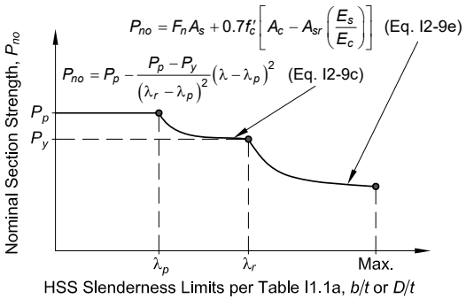
Figure description:
Nominal Section Strength Behavior for HSS Sections HSS Slenderness Limits per Table I1.1a, or
Nominal Section Strength, vs. HSS Slenderness Limits
Annotations
- (Eq. I2-9c (text_label - position: points to curve between and ))))
- (Eq. I2-9e (text_label - position: points to curve for )))
- (text_label - position: y-axis intercept and plateau level)
- (text_label - position: y-value at )
- (text_label - position: x-axis transition point 1)
- (text_label - position: x-axis transition point 2)
- Max. (text_label - position: x-axis maximum limit)
| HSS Slenderness Limits (), or | Nominal Section Strength () | Segment / Equation |
|---|---|---|
| 0 | Compact Section | |
| Compact Section Limit | ||
| (where ) | )) | Noncompact Section (Eq. I2-9c) |
| Noncompact Section Limit | ||
| (where ) | ) | Slender Section (Eq. I2-9e) |
| Max. | ) | Maximum Slenderness Limit |
Notes: The chart illustrates the transition of nominal section strength across different slenderness regimes: compact, noncompact, and slender, as defined by AISC specifications.
Fig. C-12.1. Nominal axial strength, , versus HSS wall slenderness.
The nominal axial strength, , of composite compression members, including length effects, may be determined using Equations I2-2 and I2-3, while using from Equation I2-12 to account for composite section rigidity and to account for the effects of local buckling as described in the preceding. This approach is different than the one used for HSS found in Section E7. The approach in Section E7 was not implemented for filled compression members because (a) their axial strength is governed significantly by the contribution of the concrete infill, (b) concrete inelasticity occurs within the compression member failure segment irrespective of the buckling load, and (c) the calculated nominal strengths compare conservatively with experimental results (Lai et al., 2014; Lai and Varma, 2015).
I2.2c Tensile Strength
As for encased compression members, this section specifies the tensile strength for filled composite members. Similarly, while the provision focuses on the limit state of yielding of the gross area, where appropriate, consideration should also be given to other tensile strength and connection strength limit states as specified in Chapters D and J.
I2.3 Composite Plate Shear Walls
I2.3a Compressive Strength
For out-of-plane buckling of composite walls, will typically be equal to the story height. For in-plane buckling of composite walls, stability will typically not govern. Design Guide 38 (Varma et al., 2022) provides additional guidance.