C-I7I7 Composite diaphragms and collector beams
PDF page 527 · AISC 360-22
In composite construction, floor or roof slabs consisting of composite metal deck and concrete fill are typically connected to the structural framing to form composite
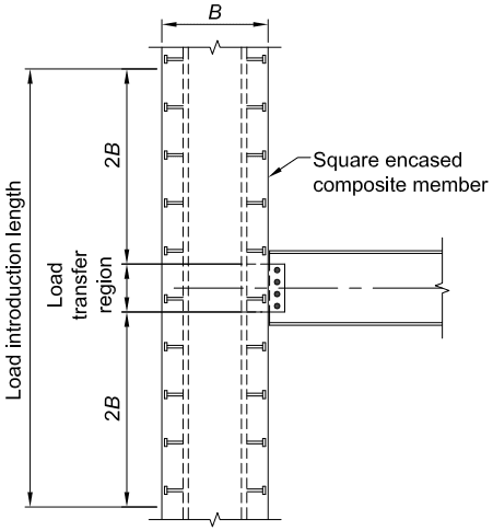
Figure description:
Diagram Title: Fig. C-I6.1. Load transfer region and load introduction length.
Key Entities:
- Square encased composite member: Vertical structural element with width .
- Horizontal beam: Connected to the vertical composite member at the load transfer region.
- Shear connectors: Anchors distributed vertically along the internal steel section of the composite member.
Key Dimensions and Regions:
- : Width of the square encased composite member.
- Load transfer region: The central vertical zone where the beam connects to the member.
- Load introduction length: The total vertical distance required for load distribution, extending above and below the load transfer region.
- : The specific vertical distance defining the extent of the load introduction length from the boundaries of the load transfer region.
Fig. C-16.1. Load transfer region and load introduction length.
diaphragms. Diaphragms are horizontally spanning members, analogous to deep beams, which distribute lateral loads from their origin to the lateral force-resisting system either directly or in combination with load transfer elements known as collectors or collector beams (also known as diaphragm struts and drag struts).
Diaphragms serve the important structural function of interconnecting the components of a structure to help it behave as a unit. Diaphragms are commonly analyzed as simple-span or continuously spanning deep beams, and hence, are subjected to shear, moment, and axial forces, as well as the associated deformations. Further information on diaphragm classifications and behavior can be found in AISC (2018a) and SDI (2015).
Composite Diaphragm Strength. Diaphragms should be designed to resist all forces associated with the collection and distribution of lateral forces to the lateral force-resisting system. In some cases, loads from other floors should also be included, such as at a level where a horizontal offset in the lateral force-resisting system exists. Several methods exist for determining the in-place shear strength of composite diaphragms. Three such methods are as follows:
- (a) As determined for the combined strength of composite deck and concrete fill, including the considerations of composite deck configuration, as well as type and layout of deck attachments. One publication that is considered to provide such guidance is the SDI Diaphragm Design Manual (SDI, 2015). This publication covers many aspects of diaphragm design, including strength and stiffness calculations. Calculation procedures are also provided for alternative deck-to-framing connection methods, such as puddle welding and mechanical fasteners in cases where anchors are not used. Where stud anchors are used, stud shear strength values shall be as determined according to Section I8.
- (b) As the thickness of concrete over the steel deck is increased, the shear strength can approach that for a concrete slab of the same thickness. For example, in composite floor deck diaphragms having cover depths between 2 in. (50 mm) and 6 in. (150 mm), measured shear stresses on the order of , where is in units of ksi, have been reported. In such cases, the diaphragm strength of concrete metal deck slabs can conservatively be based on the principles of reinforced concrete design (ACI, 2019) using the concrete and reinforcement above the metal deck ribs and ignoring the beneficial effect of the concrete in the flutes.
(c) Results from in-plane tests of filled diaphragms.
Collector Beams and Other Composite Elements. Horizontal diaphragm forces are transferred to the steel lateral force-resisting frame as axial forces in collector beams, which are also known as diaphragm struts or drag struts. The design of collector beams has not been addressed directly in this chapter. The rigorous design of composite collector beams is complex and few detailed guidelines exist on such members. Until additional research becomes available, a reasonable simplified design approach is provided as follows:
Force Application. Collector beams can be designed for the combined effects of axial load due to diaphragm forces, as well as flexure due to gravity and/or lateral loads. The effect of the vertical offset (eccentricity) between the plane of the diaphragm
and the centerline of the collector element results in additional shear reactions that should be investigated for design.
Axial Strength. The available axial strength of collector beams can be determined according to the noncomposite provisions of Chapter D and Chapter E. For compressive loading, collector beams are generally considered unbraced for buckling between braced points about their strong axis and fully braced by the composite diaphragm for buckling about the weak axis. The limit state of flexural-torsional buckling with bracing offset from the shear center, as addressed in Section E4, may also apply.
Flexural Strength. The available flexural strength of collector beams can be determined using either the composite provisions of Chapter I or the noncomposite provisions of Chapter F. It is recommended that all collector beams, even those designed as noncomposite members, should consider shear connector slip capacity as discussed in Commentary Section I3. This recommendation is intended to prevent designers from utilizing a small number of anchors solely to transfer diaphragm forces on a beam designed as a noncomposite member. Anchors designed only to transfer horizontal shear due to lateral forces will still be subjected to horizontal shear due to flexure from gravity loads superimposed on the composite section and could become overloaded under gravity loading conditions. Overloading the anchors could result in loss of stud strength, which could inhibit the ability of the collector beam to function as required for the transfer of diaphragm forces due to lateral loads.
Interaction. Combined axial force and flexure can be assessed using the interaction equations provided in Chapter H. As a reasonable simplification for design purposes, it is acceptable to use the noncomposite axial strength and the composite flexural strength in combination for determining interaction.
Shear Connection. It is not required to superimpose the horizontal shear due to lateral forces with the horizontal shear due to flexure for the determination of steel anchor requirements. The reasoning behind this methodology is twofold. First, the load combinations as presented in ASCE/SEI 7 (ASCE, 2022) provide reduced live load levels for load combinations containing lateral loads. This reduction decreases the demand on the steel anchors and provides additional capacity for diaphragm force transfer. Secondly, horizontal shear due to flexure in a simply supported member flows in two directions. For a uniformly loaded beam, the shear flow emanates outward from the center of the beam as illustrated in Figure C-I7.1(a). Lateral loads on collector beams induce shear in one direction. As these shears are superimposed, the horizontal shears on one portion of the beam are increased and the horizontal shears on the opposite portion of the beam are decreased as illustrated in Figure C-I7.1(b). In lieu of additional research, it is considered acceptable for the localized additional loading of the steel anchors in the additive beam segment to be considered offset by the concurrent unloading of the steel anchors in the subtractive beam segment up to a force level corresponding to the summation of the nominal strengths of all studs placed on the beam. It is considered that the shear connectors in typical practical configurations possess an adequate degree of slip capacity to accommodate this mechanism.