C-I4I4 Shear
PDF page 516 · AISC 360-22
I4.1 Encased Composite Members
Three methods for determining the shear strength of encased composite members are provided:
- (a) The intent is to allow the designer to ignore the concrete contribution entirely and simply use the provisions of Chapter G with their associated resistance or safety factors.
- (b) When using only the strength of the reinforcing steel and concrete, a resistance factor of 0.75 or the corresponding safety factor of 2.00 is to be applied, which is consistent with ACI 318.
- (c) When using the strength of the steel section in combination with the contribution of the transverse reinforcing bars, the nominal shear strength of the steel section alone should be determined according to the provisions of Chapter G and then combined with the nominal shear strength of the transverse reinforcement as determined by ACI 318. This combined nominal strength should then be multiplied by an overall resistance factor of 0.75 or divided by the safety factor of 2.00 to determine the available shear strength of the member.
Though it would be logical to suggest provisions where both the contributions of the steel section and reinforced concrete are superimposed, there is insufficient research available to justify such a combination.
I4.2 Filled Composite Members
The shear strength of circular and rectangular filled composite members in flexure is calculated in accordance with this section. Values of have been established and calibrated considering experimental results (Kenarangi et al., 2021), and data from cyclic testing (Nakahara and Tsumura, 2014; Bruneau et al., 2018; Kenarangi and Bruneau, 2020a, 2020b) and monotonic loading (Xu et al., 2009; Xiao et al., 2012; Lehman et al., 2018a, 2018b; Ye et al., 2016) for composite filled round HSS and filled rectangular sections (Koester, 2000; Fischer and Varma, 2015a).
Equation I4-1 combines the plastic shear strength of the steel HSS and the contribution of the concrete fill, which depends on the shear span-to-depth ratio illustrated in Figure C-I4.1. Research has demonstrated that the concrete fill adds substantially to the shear strength of filled composite members. Specimens with and without internal reinforcement were shown to exhibit similar cyclic shear strengths in experiments by Bruneau et al. (2018). The contribution of the internal reinforcement to the total shear strength was found to be marginal compared to the strength provided by the steel HSS, and is, therefore, not part of the design equations.
For very short shear spans, the shear behavior is governed by the formation of a strut in the infill concrete. For example, for circular cross sections, the contribution of this diagonal has been reported to be largest for shear span-to-diameter ratio, , of 0.25 (Bruneau et al., 2018; Kenarangi and Bruneau, 2020b), progressively decreasing for smaller or greater values of this ratio.
An adequate development length must be present on both sides of a shear region where greater than 1 is considered. This permits the development of the diagonal strut, which typically flows between compression zones on both sides of the high shear region. Lehman et al. (2018a, 2018b) recommends the use of a minimum development length of 1 times the diameter of a filled round HSS beyond the point of zero moment to the point of maximum moment to achieve the full plastic capacity of the member.
I4.3 Composite Beams with Formed Steel Deck
A conservative approach to shear provisions for composite beams with steel headed stud or steel channel anchors is adopted by assigning all shear to the steel section in accordance with Chapter G. This method neglects any concrete contribution and serves to simplify design.
I4.4 Composite Plate Shear Walls
The in-plane shear behavior of composite plate shear walls is governed by the plane stress behavior of the plates and the orthotropic elastic behavior of concrete cracked in principal tension. Varma et al. (2014) and Seo et al. (2016) discuss the
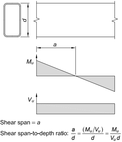
Figure description:
Structural Beam Analysis Moment and Shear Diagrams with Shear Span Definition
Moment Diagram (
Annotations
- Shear span () (text_label - position: horizontal distance from left support to inflection point)
- (text_label - position: y-intercept at )
| Distance () | Moment () |
|---|---|
| 0 | |
| 0 | |
Shear Diagram (
Annotations
- (text_label - position: constant shear value)
| Distance () | Shear () |
|---|---|
| 0 | |
Notes: The figure illustrates the relationship between moment and shear in a structural beam. The shear span is the distance from a point of maximum moment to the point of zero moment. The equations provided are: Shear span = ; Shear span-to-depth ratio: . The beam cross-section has a depth .)
Figure C-I4.1. Shear span-to-depth ratio for filled composite flexural members.
in-plane shear behavior of composite plate shear walls. The nominal shear force corresponding to the onset of yielding of the steel plates is given by Equation I4-2. The corresponding principal compressive stress in the cracked (orthotropic) concrete is less than for typical composite walls with reinforcement ratios, , less than or equal to 10%. For walls with very high reinforcement ratios (in other words, walls with very thick steel plates compared to overall thickness), the concrete principal compressive stress can be the limiting failure criterion (Seo et al., 2016; Varma et al., 2014). The ultimate shear strength of composite walls, beyond the yielding of the steel plates, depends on the compression strut failure of the cracked concrete infill and can be 20 to higher (Booth et al., 2019).
The out-of-plane shear strength of composite plate shear walls rarely governs design. However, if perimeter composite plate shear walls are used on the exterior surfaces of the building, then out-of-plane shear strength may have to be checked for wind pressure. Equations for calculating out-of-plane strength are included in the AISC Specification for Safety-Related Steel Structures for Nuclear Facilities, Section N9.3.5 (AISC, 2018b). The development of these equations is presented in Sener and Varma (2014) and Sener et al. (2015), and their use is demonstrated in AISC Design Guide 32 (Bhardwaj and Varma, 2017).