CL™ Self-Clinching Nuts
Installation – SP™/SMPP™ Nuts (1)
PDF page 35 · PEM Fastener Catalogue
- Prepare properly sized mounting hole in sheet. Do not perform any secondary operations such as deburring.
- Place fastener into the recommended counterbore anvil hole and place the mounting hole (preferably the punch side) over the shank of the fastener as shown in diagram.
- With installation punch and anvil surfaces parallel, apply squeezing force until the head of the nut comes into contact with the sheet material.
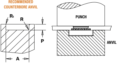
Drawing callouts: Recommended counterbore anvil — Punch; Anvil; A; P; R; R1.
PEMSERTER® Installation Tooling
SP™ Nuts
Unified
| Thread Code | Anvil Dimensions (in.) | Anvil Part Number | Punch Part Number | |||
|---|---|---|---|---|---|---|
| A ±.002 | P +.000 –.001 | R Max. | R1 +.005 | |||
| 440 | .255 | .064 | .010 | .005 | 8012821 | 975200048 |
| 632 | .286 | .064 | .010 | .005 | 8012822 | |
| 832 | .317 | .082 | .010 | .005 | 8012823 | |
| 024/032 | .348 | .082 | .010 | .005 | 8012824 | |
| 0420 | .443 | .163 | .010 | .005 | 8012825 | 8003076 |
| 0518 | .505 | .230 | .010 | .005 | 8015359 | |
| 0616/0624 | .570 | .263 | .010 | .005 | 8015863 | |
Metric
| Thread Code | Anvil Dimensions (mm) | Anvil Part Number | Punch Part Number | |||
|---|---|---|---|---|---|---|
| A ±0.05 | P –0.03 | R Max. | R1 +0.13 | |||
| M2 | 6.48 | 1.63 | 0.25 | 0.13 | 8012821 | 975200048 |
| M2.5-0 | 6.48 | 1.42 | 0.25 | 0.13 | 8019477 | |
| M2.5-1,-2 | 6.48 | 1.63 | 0.25 | 0.13 | 8012821 | |
| M3 | 6.48 | 1.63 | 0.25 | 0.13 | 8012821 | |
| M3.5 | 7.26 | 1.63 | 0.25 | 0.13 | 8012822 | |
| M4 | 8.05 | 2.08 | 0.25 | 0.13 | 8012823 | |
| M5 | 8.84 | 2.08 | 0.25 | 0.13 | 8012824 | |
| M6 | 11.25 | 4.14 | 0.25 | 0.13 | 8012825 | 8003076 |
| M8 | 12.83 | 5.41 | 0.25 | 0.13 | 8015360 | |
| M10 | 17.58 | 7.47 | 0.25 | 0.13 | 8015886 | |
SMPP™ Nuts
Unified
| Thread Code | Anvil Dimensions (in.) | Anvil Part Number | Punch Part Number | |||
|---|---|---|---|---|---|---|
| A ±.002 | P +.000 –.001 | R Max. | R1 +.005 | |||
| 256 | .223 | .060 | .010 | .005 | 8020023 | 975200048 |
| 440 | .233 | .060 | .010 | .005 | 8021386 | |
| 632 | .255 | .060 | .010 | .005 | 8020024 | |
Metric
| Thread Code | Anvil Dimensions (mm) | Anvil Part Number | Punch Part Number | |||
|---|---|---|---|---|---|---|
| A ±0.05 | P –0.03 | R Max. | R1 +0.13 | |||
| M2.5 | 5.66 | 1.27 | 0.25 | 0.13 | 8020025 | 975200048 |
| M3 | 5.9 | 1.27 | 0.25 | 0.13 | 8021474 | |
| M3.5 | 6.48 | 1.27 | 0.25 | 0.13 | 8020026 | |
(1) For best results, we recommend using the installation punch and anvil shown. Deviations from recommended installation tooling may result in sheet distortion and reduced performance.
NOTE: Variations in hole preparation, installation tooling, installation force, and sheet material type, thickness, and hardness will affect both performance and tooling life.