PEM RT® Free-Running Locknuts
PDF page 30 · PEM Fastener Catalogue

Free-running locking feature allows screw to turn freely until clamp load is applied. If the tightening force is removed, these nuts no longer provide any torsional resistance to rotation until clamp load is reapplied.
- Resistant to vibrational loosening.
- Back side of panel is flush or sub-flush for screw installation.
- Locking feature reusability is not affected by number of on/off cycles.
- Uses same mounting hole and installation tooling as standard S™ nuts.
- Recommended for use in steel or aluminum sheets HRB 80 / HB 150 or less.
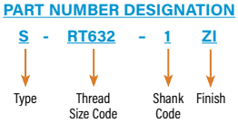
Part Number Designation
| Part Number | Type | Thread Size Code | Shank Code | Finish |
|---|---|---|---|---|
| S–RT632–1ZI | S | RT632 | 1 | ZI |
PEM RT® free-running locking feature can be added to other PEM® internally threaded nuts.
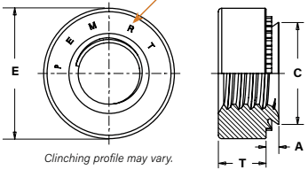
Drawing callouts: E, C, A, T. PEM RT® Stamp (Registered Trademark). Clinching profile may vary.
Unified — all dimensions are in inches.
| Thread Size | Type | Thread Code | Shank Code | A (Shank) Max. | Rec. Min. Sheet Thickness(1) | Hole Size In Sheet +.003 −.000 | C Max. | E ±.010 | T ±.010 | Min. Dist. Hole ℄ To Edge |
|---|---|---|---|---|---|---|---|---|---|---|
| .112-40 (#4-40) | S | RT440 | 0 | .030 | .030 | .166 | .165 | .250 | .070 | .19 |
| 1 | .038 | .040 | ||||||||
| 2 | .054 | .056 | ||||||||
| .138-32 (#6-32) | S | RT632 | 0 | .030 | .030 | .1875 | .187 | .280 | .070 | .22 |
| 1 | .038 | .040 | ||||||||
| 2 | .054 | .056 | ||||||||
| .164-32 (#8-32) | S | RT832 | 0 | .030 | .030 | .213 | .212 | .310 | .090 | .27 |
| 1 | .038 | .040 | ||||||||
| 2 | .054 | .056 | ||||||||
| .190-32 (#10-32) | SS | RT032 | 0 | .030 | .030 | .250 | .249 | .340 | .090 | .28 |
| 1 | .038 | .040 | ||||||||
| 2 | .054 | .056 | ||||||||
| .250-20 (1/4-20) | S | RT0420 | 0 | .045 | .047 | .344 | .343 | .440 | .170 | .34 |
| 1 | .054 | .056 | ||||||||
| 2 | .087 | .090 | ||||||||
| .313-18 (5/16-18) | S | RT0518 | 1 | .054 | .056 | .413 | .412 | .500 | .230 | .38 |
| 2 | .087 | .090 |
Metric — all dimensions are in millimeters.
| Thread Size x Pitch | Type | Thread Code | Shank Code | A (Shank) Max. | Rec. Min. Sheet Thickness(1) | Hole Size In Sheet +0.08 | C Max. | E ±0.25 | T ±0.25 | Min. Dist. Hole ℄ To Edge |
|---|---|---|---|---|---|---|---|---|---|---|
| M3 x 0.5 | S | RTM3 | 0 | 0.77 | 0.8 | 4.22 | 4.2 | 6.35 | 1.5 | 4.8 |
| 1 | 0.97 | 1 | ||||||||
| 2 | 1.38 | 1.4 | ||||||||
| M4 x 0.7 | S | RTM4 | 0 | 0.77 | 0.8 | 5.41 | 5.38 | 7.87 | 2 | 6.9 |
| 1 | 0.97 | 1 | ||||||||
| 2 | 1.38 | 1.4 | ||||||||
| M5 x 0.8 | SS | RTM5 | 0 | 0.77 | 0.8 | 6.35 | 6.33 | 8.64 | 2 | 7.1 |
| 1 | 0.97 | 1 | ||||||||
| 2 | 1.38 | 1.4 | ||||||||
| M6 x 1 | S | RTM6 | 00 | 0.89 | 0.92 | 8.75 | 8.73 | 11.18 | 4.08 | 8.6 |
| 0 | 1.15 | 1.2 | ||||||||
| 1 | 1.38 | 1.4 | ||||||||
| 2 | 2.21 | 2.29 | ||||||||
| M8 x 1.25 | S | RTM8 | 1 | 1.38 | 1.4 | 10.5 | 10.47 | 12.7 | 5.47 | 9.7 |
| 2 | 2.21 | 2.29 |
(1) For maximum performance, we recommend that you use the maximum shank length for your sheet thickness.
Vibration Test Results
The graph represents the clamp load of the joint versus the amount of cycles during transverse vibration testing for an PEM RT® free-running locknut, a standard S nut, a split ring lock washer and Loctite Red 271.
Graph: Preload (kN), axis 0 to 8, versus Number of Cycles, axis 0 to 2000 (ticks 0, 500, 1000, 1500, 2000). Series: Standard S Nut Preload; PEM RT® Average Preload; Split Ring Lock Washer; Loctite Red 271.
Testing conditions:
- Transverse vibration testing.
- M6 thread size nuts, average of 30 pieces.
- Clamp load applied using metric property class 12.9 screws.
- Nuts tested until loss of clamp load or 2,000 cycles is reached.
Details on PEM RT® vibration resistant thread technology can be found on our web site at: https://www.pemnet.com/files/design_info/techsheets/RT_Thread_Form.pdf